


Progress with Swash-Oate Engines
Page 54
If you've noticed an error in this article please click here to report it so we can fix it.
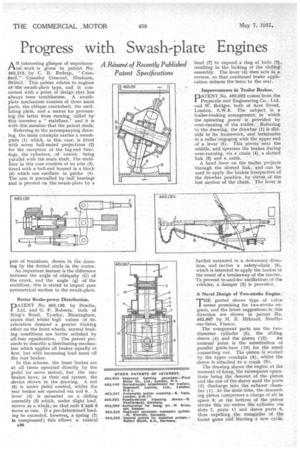
AN interesting glimpse of experimental. work is given in patent No. 463,215, by C. B. Redrup, " Cramlord," Cransley Crescent, Henleaze, lAriitol. This patent relates to engines of ,the rswash-plate type, and is concerned with a point of design-tbat has always been troublesome. A swashplate mechanism consists of three main parts, the oblique crankshaft, the oscillating 'plate, and a means for preventing the latter from turning, called by this inventor a "stabilizer," and it is with this member that the patent deals.
Referring to the accompanying drawing, the main crankpin carries a swashplate (1) which, in this case, is fitted with seven ball-ended projections (2) for the reception of the big-end bearings, the cylinders, of course, being parallel with the main shaft. The stabilizer in this case consists of an arm (3), fitted with a ball-end housed in a block (4) which can oscillate in guides (5). The arm is journalled by ball bearings and is pivoted on the swash-plate by a pair of trunnions, shown in the drawing by the dotted circle in the centre.
An important feature is the difference between the angle of obliquity (G) of the crank, and the angle (g) of the stabilizer; this is stated to impart pure symmetrical motion to the swash-plate.
Better Brake-power Distribution.
PATENT No. 463,139, by Bendix, Ltd. and G. P. Roberts, both of King's Road, Tyseley, Birmingham, states that whilst high values of deceleration demand a greater braking effort on the front wheels, normal braking conditions are better satisfied by all-four equalization. The patent proceeds to describe a distributing mechanism which applies all brakes equally at first, but with increasing load eases off the rear brakes.
In this scheme, the front brakes are at all times operated directly by the pedal (or servo motor), but the rear brakes have, in their rod system, the device shown in the drawing. A rod (5) is under pedal control, whilst the rear brakes are operated via rod 6. A lever (4) is mounted on a sliding assembly (3) which, under slight load, moves as a whole, .so that rods 5 and 6 move as one. If a pre-determined loading be exceeded, however„, a spring (2) is compressed ; this allows a conical A36
head (7) to expand a ring of balls (1)4 resulting in the locking of the sliding assembly. The lever (4) then acts as a reverse, so that continued brake application reduces the force to the rear.
Improvements in Trailer Brakes,
PATENT No. 463.022 comes from the Projectile and Engineering Co., Ltd. and W. Bridges, both of Acre Street, London, S.W.8. The subject, is a trailer-braking arrangement, in which the operating .power is provided by over-running of the trailer. Referring to the drawing, the drawbar (1) is slidable in its framework, and terminates in a collar engaging.with the upper end of a lever (5). This pivots near the middle, and operates the brakes during over-running, via a chain (4), a slotted link (3) and a cable.
A hand lever on the trailer projects through the slotted link,and can be used to apply the brakes irrespective of the drawbar position, by virtue of the lost motion of the chain. The lever is A Novel Design of Two-stroke Engine.
-rHE ported sleeve type of valve 1 seems promising for two-stroke engines, and the latest suggestions in this direction are shown in patent No. 462,867 by H. E. Hebrard, Neuillysur-Seine, France.
The component parts are the twodiameter cylinder (5), the sliding sleeve (4) and the piston (12). An unusual point is the substitution of parallel guide-bars (10) for the usual connecting rod. The piston is worked by the upper crankpin (8), whilst the sleeve is attached to a crank (9).
The drawing shows the engine at the moment of firing, 'the subsequent operations being the descent of the piston and the rise of the sleeve until the ports (2) discharge into the exhaust chamber (1). At the same time, the descending piston compresses a charge of air in space 3; at the bottom of the piston stroke this air -enters the 'cylinder via slots 7, ports 11 and sleeve ports 6, thus expelling the remainder of the burnt gases arid Starting a new cycle.