


PORTABLE PRODUCER-GAS PLANTS.
Page 30
If you've noticed an error in this article please click here to report it so we can fix it.
A Résumé of Recently Published Patents.
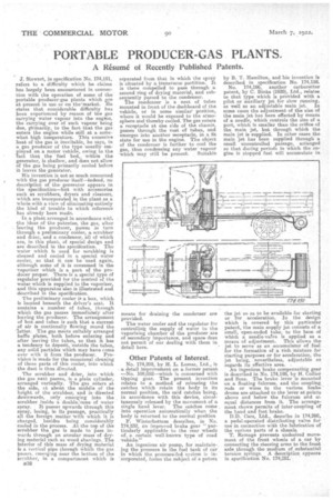
J. Stewart, in specification No. 174,191, refers to a difficulty which les chums has largely been encountered in connection with the operation of some of the portable producer-gas plants which are at present in use or on the-market. Ile states that considerable difficulty has peen experienced by reason of the gas carrying water vapour into the engine, the carrying over of such vapour being due, ifrimarily, to the fact that the gas enters the engine while still at a somewhat high temperature. This excessive heat of tire
e gas s inevitable, he says, in a gas producer of the type usually employed on a motor vehicle, owing to the "fact that the fuel bed,, within the generator, is shallow, and does not allow of the gas being primarily cooled before it leaves the generator.
His invention is not, so much concerned with the gas producer' itself—indeed, no description of the' generator appears in the specification—but with accessories such as scrubbers, dryers and cleaners, which are incorporated in the plant as a whole with a view of eliminating entirely the kind of trouble LO which reference has already been made. , in a plant arranged in accordance with -the ideas of the patentee, the gas, after leaving the producer, passes in turn "through a preliminary cooler, a scrubber and drier, and a condenser, all of which are, in this plant, of special design and are described in the specification. The water which is used for scrubbing is cleaned and cooled in a special water cooler, so that it cars be used again, although some of it is consumed in the vaporizer which is a part of the producer proper. There is a special type of regulator provided for the control of the water. which is supplied to the vaporizer, and this 'apparatus also is illustrated and described m the specification.
The preliminary cooler is a box, which is located beneath the driver's seat. It contains a .number of tubes, through which the gas passes immediately after leaving the producer. The arrangement of box and tubes is such that a current of air is continually flowing round tho 'latter. The gas meets suitably arranged baffle plates, both before entering and after leaving the tubes, so that it has a tendency to deposit, outside the tubes, any solid particles which may have come over with it from the producer. Provision is made for the occasional cleaning of those parts of this cooler, into which the dust, is thus directed.
The scrubber and drier, into which the gas next passes, is a plain cylinder, arranged vertically. The gas enters at the side, et about the middle of the height of the scrubber, and is directed downwards, only emerging into the scrubber inside a double.,'reene of water spray. It passel upwards through this spray, losing, in its passage, practically all the foreign matter -with which it is charged, besides being considerably cooled in the process. At the top of the 'scrubber the gas is made to pass inwards through an annular mass of drying material such as wood shavings. The interior of this mass of drying material is a eertical pipe through which the gas passes. emerging near the bottom of the scrubber, in a compartment which is
13a2 separated from that in which the spray is situated by a transverse partition. It is there compelled to pass through a second ring of drying material, and subsequently passed te the condenser. The condenser is a nest, of tubes mounted in front of the dashboard of the. vehicle, or in some similar' position, where it would be exposed to the atmosphere and thereby cooled. The gas enters a receptacle at one side of the chassis, passes through the nest of tubes, and emerges into another receptacle, in a fit state for use in the engine. The object of the condenser is further to cool the gas, thus condensing any water vapour -which may still be present. Suitable means for draining the condenser are provided.
The water cooler and the regulator for eoritrollin the supply of water to the vaporizing chamber of the producer are of secondary importance, and space does not permit of our dealing with them in "detail here.
Other Patents of Interest.
No. 174,209, by II. L. tomes, Ltd., is a detail improvement on a former patent —No. 108,052—which is concerned with tipping gear. The present invention relates to a method of releasing the catches which retain the body in its normal position, the said catches being, in accordance with this device, simultaneously released by the movement. of a single hand lever. The catches come into operation automatically when the body is returned to the normal position
F. Winterbottom describes, in No. 174,252, an improved brake gear " particularly applicable to the rear wheels of. a certain well-known type of road vehicle."
An ingenious air pump, for maintaining the pressure in the fuel tank of car in which the pressure-fed system is incorporated, forms the subject of a patent
by B. T. Hamilton, and his invention is described in specification No. 174,158.
No. 174,166, another carburetter patent, by C. Binks (1920), Ltd., relates to that type which is provided with a• pilot or auxiliary jet for slow running, as well as an adjustable main jet. In some cases the adjustment of the size of the main jet has been effected by means of a needle, which controls the size of a port, which is smaller than the orifice of the main jet, but through which the main jet is supplied. In other cases the main jet has been supplied through a small uncontrolled passage, arranged so that during periods in which the engine is stopped fuel will accumulate in the jet so as to be available for starting or for acceleration. In the design which is covered by this particular patent, the main supply jet consists of a small, open-ended tube, to the hare of which a needle-vafve is applied as a means of adjustment. This allows tho jet to serve as an accumulator of fuel for the formation of a rich mixture.for starting purposes or for acceleration, the jet being, nevertheless, adjustable as regards its effective area. • An ingenious brake compensating gear is described in No. 174,1813, by H. C.ollier
an i d Sons. The brake lever s mounted on a floating fulcrum, and the coupling rods or wires to the various brake" drums are attached to the lever at points above and below the fulcrum and at equal distances from it,. The arrangement shown permits of inter-coupling of the hand and foot brake.
D.D. Cars, Ltd., describe in 174,260,_ a pedal-operated distributing valve for use in connection with the lubrication of the various parts of a chassis. •
T. Ramage prevents undesired movement of the front wheels of a car by connecting the steering arms to the front axle through the medium of substantial tension Speerigs. A description appears in specification No. 174,281. "