


HINTS ON MAINTENANCE.
Page 28
Page 29
If you've noticed an error in this article please click here to report it so we can fix it.
Hcnii to Get the Best Out of a Vehicle, to Secure Reliability and to Avoid Trouble
' ONTRIBUTIONS are invited for this page from mechanics, works staff and draughtsmen, and fleet managers, drivers, garage foremen, and
-will be paid for on a generous scale. Every system, make, and typo of commercial motor vehicle will be dealt with, and the in a t te r should he written with a view to the disclosure of workshop and garage practiee in the maintenance of a vehicle—practices which, whilst they may be quite normal, are peculiar to the particular vehicle and may not be generally known to those responsible for its running. Expedi*nts and suggestions for overcoming roadside and other troubles are covered in the following page, headed "Roadside and Garage." Communications should be addressed to " The Editor, The Commercial Motor, 7-15, Rosebery Avenue, London, KC. I."
175,—Renovating the Front Wheels of a Leyland Chassis.
The front wheels of some Leyland vehicles are built up with inside and outside plates riveted to a hub and a rim. Under the effects of vibration the rivets occasionally become loose, and the plates may wear, or even crack. When this occurs on a wheel, remove the band tyre and knock out all the rivets, thus dismantling the wheel into four parts without considering the tyre. The plates and the huh should then be welded, thoroughly cleaned, new holes drilled, and the centre hales bored out to suitthe hub. The parts can then be reassembled, using I iii. diameter bolts of the required length, and good soring washers, after which the tyre can be refitted.
176.—Care of the Brakes on the Foden Steam Wagon.
Some of the Foden steam wagons are fitted with a flywheel brake. This is intended for temporary or emergency use enly, and must not be used continuously on hills, as excessive friction causes the rim of the flywheel to become hot, thus expanding stresses are set up which ma k result in a fracture, possibly with serious consequences.
The old type drum brake fitted on the rear axle requires adjustment as the lining wears. To allow for this, the connecting links at the bottom of the band are provided with holesat various centres. The internal-expanding ring brake also requires adjustment as the, lining wears. To effect this put the brake on as tightly as possible and place a wedge between the ends of the expanding ring, release the pedal, take the pin out of the toggle plates, set the pedal in the third notch from the top of the quadrant, lengthen the toggles so that the pins can be replaced in the plates, remove the wedge, and release the pedal. The side rods should be adjusted .only when the axle position ia altered. In those types fitted with the expanding shoe brake this must be adjusted by the side rods on'ly. To take off the shoes for refining, remove thefnins, when the bottom shoe can he taken out and the upper shoe passed into bottom position for removal.
177.—Attending to the Clutch on the Bristol Chassis.
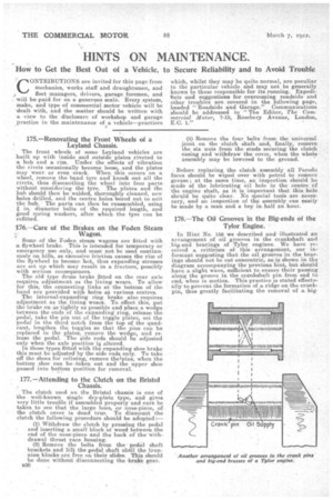
The clutch used on the Bristol chassis is one of the well-known single dry-plate type, and gives very little trouble if assembled, properly and care be taken to see that the large boss, or nose-piece, ofthe clutch cover is dead true. To dismount the clutch the following procedure should be adopted:— (1) Withdraw tha clutch by pressing the pedal and inserting a small Hoek of wood between the end of the nose-piece and the bask of the withdrawal thrust -race housing.
(2) Remove the bolts from thea pedal shaft brackets and lift the pedal shaft abtil the trunnion blocksare free on their slides. This should be done without disconnecting the brake gear. a30
(3) .Remove the four bulte from the universal joint on the clutch shaft and, finally, remove the six, nuts from the studs securing the clutch casing and withdraw the cover, when the whole
assembly may be lowered to the ground.
Before replacing the clutch assembly all Ferodo faces should be wiped over with petrol to remove grease; at the same time, an inapection should be made of the lubricating oil hole in the centre of the engine shaft, as it is important that this hole should be quite clear. No special tools are necessary, and an inspection of the assembly can easily be made by a man and a boy in half an hour.
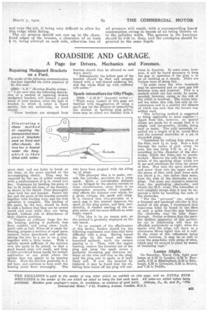
178.—The Oil Grooves in the Big-ends of the Tylor Engine.
in Hint No. 15a we described and illustrated an arrangement of oil grooves in the crankshaft and Iii-end bearings of TyIor engines. We have rocoved a criticism of this arrangement, our informant suggesting that the oil grooves in the hearings should not be cut concentric, as is shown in the diagram accompanying the previous hint, but should have a slight wave, sufficient to ensure their passing along the groove in the crankshaft pin from end to end, when in motion. This practice is stated effectually to prevent the formation of a ridge on the crankpin, thus greatly facilitating the removal of a big end over the pit, it being very difficult to allow for this ridge when fitting. The oil grooves should not run up to the chamfered edges of the brasses a clearance of at least n in. being allowed o each side, otherwise loss of oil pressure will result, with a corresponding heavy consumption owing to excess of oil being thrown on to the cylinder walls. The grooves in the bearings should be 3-32 in. deep, and the crankpins should he grooved to the same depth.