


OVERHAULING THE HALLEY.
Page 19
Page 20
Page 21
Page 22
If you've noticed an error in this article please click here to report it so we can fix it.
No. 20.—The 35 h.p. Six-cylindered Type P, with Worm-driven Axle—Dismantling the Chassis—Dealing With the Units—Adjusting Timken Bearings.
IN the 12th of our series of articles dealing with the overhauling of various chassis, we included that of the 35 h.p. chain-driven Halley, but at that time the six-cylipdered type P model had not been sufficiently long in service for examples to require complete overhauling, and we, therefore, delayed dealing with this model until such time as sufficient experience in this connection had been
gained. This is now the case. .
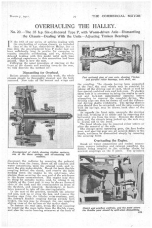
Following the usual procedure of starting at the .front of the chassis and working towards the rear, we will describe the method of-
Dismantling for Overhaul.
Before actually commencing this work, the whole' chassis should be thoroughly cleaned and the body removed. Now take off the bonnet and wings and
disconnect the radiator by removing the pedestal brackets from the frame, throw off all controls and water connections, undo the exhaust joint, and remove the side under-shields. Break the front flexible coupling behind the clutch, and remove the bolts holding down the engine to the sub-frame also slacken those securing the rear end of the sub-frame to the frame cross-members. The engine may then be slung by suitable tackle, and, by tilting it up slightly at the front end, it may be drawn forward clear of the dash and the cross-member in front of the flywheel, and removed. Incidentally, it facilitates removal to take off the starting-handle. In the ease of the gearbox, uncouple the selector rod pins, jaek up or sling the box, and remove -the bearing caps from the tubular cross-members, and, the forward flexible coupling having already been broken, the box may be dropped, the rear coupling sliding clear of the splines on the eardan shaft.
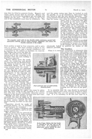
To remove the rear axle, break the rear coupling by removing the main bolts from the flexible rings, and also the centre hearing setscrews at the back of the coupling. 'the chassis having been supported at the rear, the road wheels may be removed by taking off the driving cap of each, which is held by four special combined nuts and lock-nuts. To slacken these nuts it is necessary to bring the marks in each nut and lock-nut immediately opposite before attempting to unscrew the complete device. The driving caps can then be drawn off and the differential driving shafts withdrawn. The spring shackle pins should then be extracted, and the axle, complete with its springs, may be drawn,back clear of the chassis.
As regards the front axle, uncouple the steering link rod, breaking it at either end by removing the ball-ended pin from the lever. Remove the shackle pins, and, the chassils being jacked up, the axle may be drawn out to the front.
The front wheels may be removed either before or after the removal of the axle. The change-speed operating gear, the foot brake gear, and steering gear are all secured direct to the frame, andimay be dismantled simply by removing the securing bolts.
Overhauling the Engine.
Break all water connections and control connections, remove induction and exhaust manifold, the former being coupled to the cylinder blocks by screwed couplings on the T piece. The cylinders may then be lifted in separate blocks. Magneto and -water pump should then be removed. Release the pistons by extracting the gudgeon pin end plugs and sliding out the pins. The fan pulley on the front end of the crankshaft must then be withdrawn. The
front portion is held by four setscrews, and is quite easy to remove. The inner portion is keyed to the crankshaft extension, and a special withdrawal tool is supplied by the makers to facilitate its removal. The timing case cover can then be taken off, and this will enable the bottom half of the crankcase to he dropped when the nuts holding it have been removed.
Before taking dawn the crankshaft, the connecting rode should be removed and the flywheel freed. The latter is held by nuts to the crankshaft flange, and it comes away -complete with the clutch.
Laminated shims are employed for the big-ends, and strips may be taken off these in order to make adjustments if the big-ends are slack. Die-cast, white-metal bearings are provided for the crankshaft main journals, and these can all be taken up in the usual way, the crankshaft being located, endwise by the centre bearing only. In removing the timing wheel from the camshaft, note should be taken of the position of this wheel on the splines for which purpose both wheel anti splines are marked, and in reassembling the engine care must be taken that the chain wheel on the camshaft is in a direct line with that on the crankshaft, otherwise uneven running of the chaih ensues, causing noise and wear. Should" end play develop in the camshaft, this may be taken up by the insertion of a suitable thin steel or brass washer behind the ball thrust bearing provided at the rear end.
Inspection h ouId be made of small-end bushes, etc., to ascertain if replacement be neeeasary. The whole engine is designed with a view to accessibility, and is of verb simple construction.
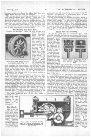
The oil pump may be removed by undoing two nuts on studs securing the pump to the top half of the crankcase. Seldom, or never, is it necessary to disturb the pump, but all passages should be cleaned by squirting paraffin through them, and the filter gauzes should be washed thoroughly before reassembling. The water pump spindle should be examined, and if pitted or worn may lie trued within reasonable limits, and the pump easing may then be bushed to suit the spindle, or, as an alternative, white-metal lined and bored to suit the new spindle 'diameter. The pump impeller should also he examined. In reassembling the pump, care must be taken when a brawn paper joint is employed that this be pierced at the small overflow hole, and the gland should be packed with tallow and hemp. The joints on the induction Tpiece between the cylinders should, be examined. When replacing the cylinder heads, the greatest care should be taken to tighten the nuts in the rotational order shown in one of the diagrams given, as otherwise it is quite possible so to strain the heads that breakage may occur or they may be sprung.
A vernier adjustment is provided. for the magneto, whilst the fan belt is tensioned by means of a spring in the bracket, the fan pillar being afterwards locked. in position by means of the setscrew provided.
The Gearbox.
When it is necessary completely to dismantle this unit, remove the selector rods ; this permits the easy withdrawal of the main shaft and countershaft by removing the end covers which house the Timken bearings. Before taking out the final motion shaft, it is necessary that the driving gear for the mileometer be withdrawn, which can be done from the side.. The gears are of the clash type. Timken bearings are employed 'throughout the gearbox, and the first and third motion shaft bearings can be taken up by reducing the 'length of the 'sleeve betweea the inner cones anti tightening up the locking nuts on the.shafts. In the ease of the layshaft, the thickness of the distance washer between the end of the shaft and the inner cones will require th be varied if the necessary adjustment here cannot be obtained by increasing the thickness of the joint be
Part sect:on& view of water pump, tween the flange of the bearing showing gland. housing and the face of. the gear
box.
It is essential that the cups should be mounted securely against their seats, and care should be taken to ensure that they are not canted in their /sigmainga. If it is necessary to fit two new cups to. a housing, great care should be, taken that these are forced home parallel with one another. The change-speed operating mechanism is fitted with case-hardened steel bushes. These have an exceptionally long life. The change-speed lever should be examined for loose or broken springs. In the case of the main shaft the gears are mounted separately on centres splined to suit the shaft, and can be replaced individually. As regards the countershaft, the wheels are also built up separately, but in this case direct on to the shaft.
Overhauling the Rear Axle.
Remove the springs. These are held to the axle 'seats by four large diameter bolts, also provided with special double nuts. Do not dismantle the springs unless this be essential, although they should be 'thoroughly cleaned a n d greased. Withdraw the brake 'drum from the rear end of the ;worm shaft. It is held by an end nut to • the
• splincd worm Rear wheel with driving ccp reshaft, and may moved, showing locking md. be removed by using the special tool supplied for this purpose ; the latter has suitable setscrews for inserting into the two in. tapped holes in the brake drum. Once the drum has been taken off, the brake shoes can easily be dismantled, and should be relined if necessary. Hardened plates are fitted at the fulcrum ends of the shoes, and these may be renewed if worn.
The main axle cover is held in position by eight nuts and studs. Remove the nuts, and the axle cover, complete with the differential gear, can be lifted out. Examine the worm and differential gearing for undue play. End-play on the differential gear can he taken up by inserting an additional or thicker washer between the thrust race at each side and the housing. Washers may also he utilized for taking up end-play on the differential pinions, The packing washers supplied are drilled in such a manner that they can only be reassembled on their original sides. This is to ensure true centring of the worm in the wheel, which is of great importance. The small actuating gear of the foot brake is located in the axle cover, and should be inspected to see that the spiral pinion is undamaged.
The Clutch.
This is of the single-disc pattern, with three pressure springs which are not intended to be adjusted, the pres sure exerted covering the full rangeof wear on the clutch fabric. The clutch sleeve bushes should be examined, and if excessively worn may easily be replaced. Incidentally, a lubricating plug is provided on the. clutch cover face.
If the oil-retaining felt washer is slack, insert a strip of fibre or similar material in its groo-ve and replace the washer. In the case 47,f the propeller shaft the fabric discs need not be replaced unless torn at tho driving bolts. The centring device wears but slightly, but should it be found excessive it may be taken up by filing or turning the face of one of the halves of the spherical housing, thus -letting the two portions together.
Front Axle and Steering.
Should the pivot pins be excessively worn, they must be replaced and not turned down. Renewable bushes are provided, and the thrust-is taken by two hardened steel buttons in each • bottom cap. Excessive lift in the pivot pins may be taken up by the insertion of packing washers under each bottom button.
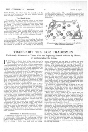
As in the case of the gearbox, the greatest attention should be paid to the ad
justment of the (Lett) Piston on engines up to Timken bearings in the wheel: No. H2199. (Right) That fitted . If . . now. excessive play is
present, the hub caps should be unscrewed, and inside them on the end of each pivot-arm will be found sIatted nut locked by a split-pin; the latter should be withdrawn. By tightening up the nut, wear on the bearing can be taken up if, at the same time, the necessary amount of metal is removed from the inner face of the nut.
In carrying out the adjustment the wheel should b2 jacked off the ground and the pivot nut tightened up against the washer, keeping the inner cone of the bearing in position until the wheel ,,beds. While doing this, revolve the wheel, to ensure that all the working surfaces come into contact. After tightening up the nut, unscrew it by between one-sixth and one-third of a turn, in order to allow the wheel to rotate freely but without side play. This adjustment can be tested by -taking a short bar and placing'the end of it between the tyre and the floor, at the same time holding one finger on the cage of the bearing. By moving the bar up and down, excessive wear or looseness can be detected. When a very,slight rock is felt and the wheel oscillates freely, the adjustment is correct. Now replace the splitpin and the hub cap. -w,NtieurzeroxoememeargritmargsvcAmL41,;s711.
The steering connections and ball Joln:s are practically selfadjusting,, being spring loaded and 'should merely be inspected a n d cleaned. T h e steering gear consists of a hardened vorm and a wheel of the full eireumfer ence. Should
-wear develop, the wheel may be turned and the steering Jever replaced on the next suitable spline, thus \taking up backlash.
The Hand Brake.
Practically the same remarks apply. -to the hand brake as to the foot brake, the shoes in this case also being provided with renewable, hardened steel plates or pads. Practically throughout the forks and levers of the hand and foot brake connections are hushed, which makes for easy replacement and inexpensive upkeep.
The radiator is of the straight gilled-tube type with removable header and bottom tank, allowing tubes to be replaced singly. The end covers of the silencer may easily be taken off and the silencer cleaned.
Reassembling.
In reassembling the chassis and coupling the clutch to the propeller shaft, great care must be taken to secure the proper adjustment of the two clutch stops provided in the coupling. Only sufficient play should be allowed to permit of the freeing of the floating member of the clutch. The rest of the reassembling can be done in practically a similar manner to that described for dismantling, and presents no special difficulties.