


Road Tanker Auxiliaries
Page 76
If you've noticed an error in this article please click here to report it so we can fix it.
AfiANY road tankers have associated 'with them a power-"driven pump or other auxiliaries for dealing with the load. Such pumps may be driven by the vehicle engine, but in . modern designs it is becoming increasingly difficult to incorporate a power take-off. A scheme 'in which a small auxiliary engine and its pumping gear are caried on a frame cross-member is shown in patent No. 772,061. (L. Riddell and Deighton's Patent Flue and Tube Co., Ltd., Vulcan Works, Pepper Road, Hunslet,-Leads, 10.) In the drawing the chassis is indicated at i and the tank at 2. A transverse sub-frame (3) 'acts as , one of the tank-carrying cradles and also carries a small auxiliary engine (4) on one side. A ptopeller 'shaft (5) takes 'the drive to the -opposite side where the pumping equipment (6) is -located. The additional engine does not add to the length of the vehicle, an important point when manoeuvrability has to be considered.
A HYDRAULIC TAPPET
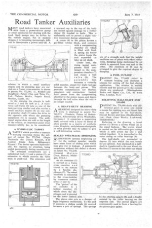
ATAPPET which provides a constant working clearance forms the subject of patent No. 772,764. . (Regie Nationale des Usines Renault, 8-10 Avenue Emile Zola, Billancourt, France.) The device-operates hydraulically, but requires no attention, being sealed permanently during manufacture.
The principal components are a cylindrical body (1) and a piston (2), an extension to which receives the valve stem or push-rod. The extension and a screwed cap in the top • of the body are sealed against leakage by a rubber sleeve' (3) bonded to both. This is sufficiently soft to permit a slight relative movement during adjustment.
A recess (4) in the piston . houses a gas-filled rubber block, and connects with a compensating chamber (5) which is filled with fluid. A spring (6) below the piston keeps the unit expanded to take up all slack.
Under load, the rising tappet compresses fluid contained in the cornpresSion chamber (7) and closes a ball valve (8). The assembly then becomes a virtually solid member, except for slight leakage between the body and piston. This provides compensation for thermal expansion and contraction. Leaked fluid passes from the compensating chamber to the piston recess, and drains through the ball valve when the unit is no longer loaded.
A HEAVY-DUTY REARING /A
A BEARING designed for heavy-duty work is disclosed in patent No. 769,573. (Frederic, Prince of Hohenzollern, Albertstrasse 10-14., Wiesbaden, Germany.) It comprises a supporting shell, covered with a layer of metal or alloy powder in a matrix of synthetic resin. Graphite, molybdenum-disulphide or mica powder may be added to give a self-lubricating action.
SEALED PNEUMATIC SPRINGING
SUSPENSION systems employing air
for the resilient member usually have some form of sliding joint which may give rise to leakage. A pneumatic suspension without this defect is shown in patent No. 772,230. (General Motors Corp., Detroit, Michigan, U.S.A.) An air container (1) is carried on a frame cross member a n d closed at the bottom' by a flexible diaphragm (2). The wheel assembly is connected to the cross-mernber by transverse control arms (3 and 4); The "piston" of the air cylinder is a hollow member_ (5) which abuts the' diaphragm and is pivoted on the lower control arm.
The piston also acts as a dannper_of high frequency oscillations. To this end it contains a sliding weight (6) centred between a pair of springs. The springs
are of a strength such that the weight oscillates out of phase-with-wheel vibrations, damping being performed by air which is squeezed from one end to the other. The closeness of fit can be arranged to give the required degree of damping.
A FUEL CUT-OFF PATENT No. 771,603 refess • to exhaust braking -and discloses a scheme for cutting off the fuel during application. The scheme is mainly electric and the patent gives the circuits which are ,employed. (Westinghouse Brake and Signal Co, Ltd., 82 York Way, London, N.1.)
RELIEVING HALF-SHAFT END LOADS
PATENT No. /70,680 deals with dif1 terential gears in axles and shows a means for resisting any end thrust that may be apPlied" to the half-shafts. (David Brown and Soni (Huddersfield), Ltd., Park Gear Works,, Lockwood, Huddersfield.)
Referring to the drawing, a bevel pinion (1) drives a crown wheel (2) in the usual fashion. The crown wheel is carried on the differential-gear casing which is split about the line 3 and bolted together. It is journalled in the outer casing on roller bearings (4).
The half-shafts are connected to sleeves (5) into which the sun, bevels (6)'are splined. Any end load on ,a halfshaft is transferred to the sun wheel via the face (7) across to the other sun wheel
by the abutting spigots (3), and is finally resisted by the roller bearing on the opposite side. The central spigots are conveniently used to form a bearing for the planet-gear spider.