


TO OBTAIN LARGER VALVE OPENINGS.
Page 68
If you've noticed an error in this article please click here to report it so we can fix it.
A Resume of Recently Published Patent Specifications.
MBE invention of a British subject, Arthur Guy Enoch, in specification No. 269,966, appears to have many points which should be worth investigation by those responsible for the design of engines. Several applications of tho invention are shown in the specification, but we have selected the one that provides for the largest valve openii g combined with the minimum movement of the valves. The cylinder is provided with a sleeve which has no ports in it, but, instead, is provided with a flange at the top which acts as a valve, seating itself on the bevelled edge of the enlarged portion of the cylinder. This valve, when open, affords communication with an annulus leading to the induction pipe, and so forms the intake.
Ii the head of the cylinder is mounted a second valve which acts as
the .exhaust. This valve has an enlarged and hollow stem, which takes the form .of a sleeve, in the centre of which is mounted the sparking plug. Both valves being practically of the same diameter as the piston, ingress and egress of the gases is permitted with great ease and at a very low velocity, whilst the movement of the valves is reduced to a minimum.
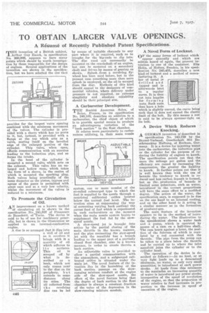
To Promote the Circulation of Oil.
AN improvement on a known method Of circulating oil is shown in the specification No. 241,937 of Francesco de Benedetti, of 'Turin. The device is said to be of use for machinery generally, but is shown in the illustration' as applied to an internal-combustion engine.
A disc is so arranged that it dips into a well of oil and as it revolves it brings with it a quantity of oil which adheres to
i t s surfaces.
This oil is scraped off by what is described as a beak, which not only comes near to the disc on its periphery, b u t extends to some distance along its sides. The oil collected from t h e revolving disc can be led by means of suitable channels to any part where it is required, such as to troughs for the big-ends to dip into. The disc need not necessarily be mounted on the crankshaft of an engine, but can be mounted on a secondary shaft and driven by means of gearing as shoWn. Splash from a revolving, flywheel has been used before, but in the present case something more than mere splash is employed, as the oil is scraped from the disc. Methods of this kind should appeal to the designers of commercial vehicles, where delivery under pressure is not required, as extreme simplicity and absolute reliability should be their principal aim.
A Carburetter Development.
THE Societe Anon yme Solex, of Seine France, in its specification No. 249:105, describes an addition to a carburetter, the chief object of which' is to provide special means to produce an advantageous variation of the "back suction" in the float chamber. It relates more particularly to carburetters utilizing, in their main nozzle
system, one or more nozzles of the so-called submerged type in which the fuel is supplied to the nozzle through a restricted calibrated orifice located below the normal fuel level. The invention aims at suppressing (by way of correcting varying back suction) the excess feed of fuel which is experienced in such carburetters at the moment when the main nozzle system begins to supplement the fuel fed by the slowspeed nozzle. A slow-speed jet is brought into action by the partial closing of the main throttle in the known manner, and the pipe connecting the slow-speed jet with the manifold has a branch leading to the upper port of a partially closed float chamber, also in a known manner, in 'order to create therein a back suction.
An adjustable valve is provided to allow a partial communication with the atmosphere, and a submerged calibrated orifice is situated under the main jet. The novel feature of the invention lies in the branching of the back suction passage on the slowrunning mixture conduit at the engine side of the slow-speed nozzle, the effect ot the novel feature being that the degree of back suction in the float chamber is always a constant fraction of the value of the depression in the slow-running mixture conduit. A Novel Form of Locknut.
OF the many forms of locknut which appear annually and which are seldom heard of again, the present in; vention is one of the quaintest. Elia Helin, of Bofors, Sweden, in his sped-, fication No. 245,455, describes a new, kind oflocknut and a method of manufacturing it. A bar of metal is drilled and tapped and is afterwards bent to a regular curve. It is then cut into lengths for forming nuts. Such nuts then have a hole which is slightly curved, the curve being such that it does not exceed the elastic limit of the bolt. By this means a nut is said to be always spanner-tight on its bolt.
...■■■■■• ■ •■■•■■■ • ■•nm....r
245,4 CS
A Device Which Reduces Knocking.
A GERMAN invention is 'described in
specification No. 243,759 by the Benzol-Verband, Gesellschaft Mit Beschraankter Haftung, of Bochum, Germany. It is a device for injecting water into the carburetter, the induction pipe or the cylinder for the purpose of reducing the liability of engines to knock.• The specification points out that the more the mileage per gallon and the efficiency are raised by increasing the compression, the greater the liability to knock. It further points out that it is well known that with the use of benzole the tendency to knock is reduced and less carbon deposit is formed, but as the, production of benzoic is limited some substitute, such as water, introduced in the correct proportions will have the same effect to a modified degree. The action of the water, the specification says, is supposed to be due on the one hand to an internal cooling, and on the other hand to it acting in a similar manner as in the formation of producer-gas.
The main -feature of the invention appears to lie in the 'method of' introducing the water. The illustration in the specification shows a water tank and a pump, which is operated by means of a cam on a half-time shaft. The cam bears against a lever, the position of the fulcrum of which is regulated by a rod connected with the throttle. The pipe from the pump can be taken to a place below the throttle and be carried up to where the inlet manifold joins the cylinder or to the cylinder head.
The operation of the device is described as follows :—At no load, or at very light loads up to a determined Minimum, no water, or only very small quantities, is introduced at each power stroke. At loads from this minimum to the maximfun an increasing quantify of water is introduced per power stroke, irrespective of the speed of revolution of the engine, so that the proportion of water relative to' fuel increases in proportion to the increase in speed of operation of the engine.