


A NEW VAPORIZER.
Page 32
If you've noticed an error in this article please click here to report it so we can fix it.
• A Résumé of Recently Published Patents.
All sorts a methods of vaporizing heavy fuels or at least, perhaps, we should say, heavy petrels, have been tried from time. to time, with more or less success, generally less. A new principle, however, seems to be involved in the design of vaporizer whiefi 2is described in specification No. 162,160 by I. H. Wilsey. The inventor deals with the problem of vaporizing a fuel such as present-day petrol, which is a mixture of spirits and hydro-carbons of differing teudencies to volatilization, and in the soletion he separates them by mechanical means, diverting the heavier fraction to an exhaust-heated chamber, while the lighter ones gy direct with the necessary admixture of air to the engine. Hepoints out that, hitherto, it has been the general practice to provide devices for
heating the entire mixture as it issues from the carburetter, whereby not only the less readily volatilized fuel fractions, but also the air and the more easily volatilized fractions are heated. This heating, besides being to some extent unnecessary, is inefficient, since it reduces the density of the mixture which is provided.
The principal factor, he points out, in obtaining the greatest volumetric efficiency from a given internal-combustion engine, is to have the densest possible gas over the inlet valve. It follows, therefore, that if maximum horse-power is desired, the. mixture should not be rarefied by a greater degree of pre-heating than is necessitated by the nature or condition of the fuel. Neglecting specific heats, only about one-fifteenth of the mixture actually requires heat treatment, the heating of the other fourteen-fifteeeths being undesirable, for the reasons already stated.
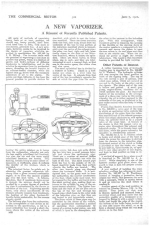
The delivery pipe from the carburetter, in the arrangement of this device as described in the specification, is led to a small cylindrical box located a short distance above the centre of the exhaust
1140 Manifold, with which is east the induction manifold. There are three branches from this box; one leads direct from the. underside of the box to that portion of the induction manifold which is immediately over the centre of the exhaust pipe: the other two lead, right and left, practically direct to the ends of . the induction manifold, where it enters the cvlindere. There are three valves in tleze pipes, one in each, and they are inter. connected in such a manner' that., as that one in the centre opens, the others close and vice versa.
The' small cylindrical box is divided by a number of baffles. There is a hori. minted one about on a level with the. centre of the box. It extends from that end of the box immediately opposite the side at which the pipe from the carbu retter enters, but does not quite divide the box into two, a small passage being left just above. the carburetter pipe. There are a number of vertical baffles connecting this horizontal one with the base of the box. The short branch pipe from the box to the middle of the exhaust manifold leads from that portion wherein the baffles are located. The other two branch pipes are disposed above the horizontal baffle. It is anticipated that, as the gases rush in from the carburetter, the heavier constituents of the fuel, which really need heat, will be trapped by the baffles and travel down the short vertical pipe, making their entrance to the cylinder by way of the exhaest-heated manifold. The lighter fractions and the bulk of the air pass out to the top of the bcre and through the branch pipe which leads to the outer ends of the induction pipe, so that they are not heated to any appreciable extent. The three valves in these pipes may be controlled by the. driver of the vehicle, but the specification describes a method of operating them automatically by means of a spring-loaded piston, one side of which is open to the atmosphere, and
the other te•the vacuum in the induction pipe. With this arrangement, when maximum power is required, the opening of the throttle or the slowing down Of the engine results in a comparatively low vacuum and moves the piston to open the two valves in the end pipes and close that in the middle ono. When the de
• mend for power is slight the reverse takes place. The result is that maximum heating is provided for light running.
Other Patents of Interest.
A rather ingenious type of' hydraulic tipping gear is described in No. 162,047 by C. Waldorf. The hydraulic cylinder and ram occupies the usual position in front of the tipping body. The top of the ram carries a .pair of pulleys, over which pass cables, which are. secured at. one end to the body, at the other end to the chassis. The piston rod of the ram
is hollow and ported. A small gear pump, enginS-driven, circulates the oil which operates the gear. An important feature of the invention is the arrangement of a three-way valve to this pump, whereby the oil is either pumped to the underside of the ram, or is allowed to bypass under control when the body is being lowered.
Franco Tosi Societh Anonima deselibee in No. 128,943 a valve gear of the type in which an oscillating valve controls the distribution of the. gases from the induction Manifold and to the exhaust passages while. the actual admission to, and egress from, the cylinder itself is by a poppet valve of the usual type. A feature of the design is that the poppet valve remains open throughout the exhaust and induction stroke. It is thereby kept cool and clean, while the power necessary for operation is considerably reduced. No. 162,013 by J. G. T. Thomas refers to brake and clutch gear of the type in which the. power for operation is derived from the vacuum in the induction pipe. Graduated control di the clutch or brake is provided so that the brake, etc., may be put half on, three-fourths on, or operated to any other greater or less degree, and kept to that position so long as required. A method of support for a wheel guard is described in No. 162,102 by A. A. Jewell. While simplicity is one of the features another good point about this guard is that it does not project outside the wheel.
A new method of tackling the mud. splashing problem has reference in specification No. 162,107 by H. Tomlinson. Instead of hanging aprotective device outside the wheel, this patentee fits each with a squeegee, which it carries before it and so removes the mud before it reaches it.
• Another aspect of the mud problem is treated by Crossley Motors, Ltd., in No. 162,210. They point out that mud is thrown upward and outward from a revolving wheel, and they claim that the protective quality of a mudguard is increased by fitting it with a small vertical baffle just, inside the edge of the guard, the bottom of the baffle being turned pp on that side nearer the wheel, so as to form a channel along which the wet mud drains on to the floor.