


A Passenger Vehicle Heating System
Page 50
If you've noticed an error in this article please click here to report it so we can fix it.
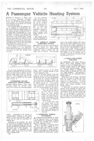
FROM E. Ottoway, J. Wicks and London passenger Transport Board, 55, Broadway, London, S.W.I, comes patent No. 637,265, describing improvements in the 'means for heating and ventilating buses.
The drawing shows the general layout as applied to a double-deck bus., Hot water from the engine-cooling system passes up pipe 1, along the floor of therupper deck, and descends to a heatexch,anger (2) located in the space under the stairs. ' A return pipe (3) leads the water back to the engine system. Inside the heat exchanger is an electric fan (4) which takes in air. from a frontal inlet (5V4raws it through the heat-exchanger and discharges it from the lower-deck ducts shown. in broken line at 6.
The top deck is provided with similar ducts as shown at, 7. An alternative intake (8) can be used if it be desired to recirculateair that has already been warmed.
If cool air be required, the air-flow is reversed in direction so that the saloon ducts are then used as intakes, the discharge taking place from an exhaust duct (9). The topping-up tank for the water system is located on the upper deck at point 10.
COMPRESSED AIR FOR OPERATING TIPPING BODIES
FL.-ROM -0fficine Viberti, Turin Italy, comes patent No. 637,532, which deals with a means for operating tipping
bodies. According to the patent, as compressed-air braking is now often fitted to large tractor-trailer outfits, it could also be used for operating the tipping gear.
Referring to the drawing, the main air reservoir (1) is piped to another one (2), the arrangement being such that the second one receives the surplus air when the brake tank is fully charged. A similiar system is provided on the trailer, which in this case is also fitted with a tipping body.
A40 As the • expansive action of the air may make control difficult, the patent suggests the use of an intermediate hydraulic system. It covers also the use of compressed-air motors for driving auxiliaries, such as pumps, loadlifting devices, an d the like.
The system is particularly applicable to multi-sectioned bodies.
AN AMERICAN RUBBER SUSPENSION SYSTEM
PNo: 637,255 comes fr'om the
• Twin Coach Co., Kent, Ohio, U.S.A., and deals with a rubber-sprung suspension system suitable for the larger sizes of vehicle. The drawings show a general layout of the whole system, also a detailed section of one of the suspension units, Pairs of brackets project from the frame to carry co-axial pivot-pins (1).
• Shackled to these are arms (2) mounted on the ends of a tubular member (3). This tube passes through a larger one (4) and the two are bonded into a unit
by 'rubber sleeves (5). The external tube is clamped at its mid-point to an axle bracket (6). Rise and fall of the axle are accommodated by the distor sion of the rubber sleeves. The arms on the ends of the inner tube are in two parts, an inner splined member (7) and the arm proper; the object being to permit prestressing of the rubber sleeve by adjusting a setscrew (8).
It is claime. d that with this system much of the complication and expense associated with the normal torsion-bar arrangement have been eliminated, and that improved stability is obtained.
A GYROSCOPIC TORQUECONVERTER A TORQUE-CONVERTER in which 1-1 the operative factor is the precessional motion of a gyroscope, is shown in patent No. 637,505, by E. Stalker, Bay City, Michigan, US.A.
When a gyroscope is spinning about one axis, and has applied to it a turning moment about an axis at rightangles, it will exert a torque about a third axis perpendicular to the first two. This is called the precessional torque, and in the present seheme, the output shaft of the unit is driven by it.. From the moment the engine commences to drive the unit, the gyroscope is. set in motion and a slight torque is applied to the road wheels. As the engine ts accelerated, this torque increases until the vehicle is set in motion, and is claimed to operate over the whole range of ratios up to 1 to I.
A NOZZLE FOR PETROL INJECTION APROBLEM with which designers are faced when adopting petrol injection is that of finding space in a modern cylinder head for the injector
as \sell as the sparking plug. Patent No. 637,584 shows a solution, the scheme being to embody the two units in a single member. The patentee is Mono-Cam. Ltd., 37, Alexandra Road, Epsom, Surrey.
Referring to the drawing, a sparking plug (1), is bored to receive the insulator (2) which is held in the usual
manner by a ring-nut (3). A lateral extension receives connection 4 for the petrol pipe, which provides timed charges of fuel.
A ball-valve (5) prevents explosion pressure from reaching the petrol line. The petrol emerges from a small spraying aperture (6) in the side of the plug end. As an alternative to screwing in, the unit can be held in position by a pair of studs in the cylinder head, lugs being provided on the side of the unit.