


External Cylinders for Hydraulic Brakes
Page 36
If you've noticed an error in this article please click here to report it so we can fix it.
A Résumé of Patent Specifications That Have Recently Been Published. Copies may be obtained from the Patent Office, Price 11each
THE expander of an hydraulic brake is often placed inside the drum but, during periods of prolonged braking, the developed beat may cause the fluid to froth. The obvious remedy is to locate the cylinder on the outside of the drum, but this leads to certain mechanical difficulties. To overcome themis the object of a design of brake shown in patent No. 561,055, by the Rover Co., Ltd., and P. Scott-Iversen, both of Chesford Grange, Kenilworth, Warwick.
If sideways stresses in the shoes are to be avoided, the expanding force should be applied in the middle of the width of the shoe, but, with an external cylinder, this is not possible; the pressure would be entirely one-sided and would tend to twist the shoes. The drawing shows a means for avoiding this trouble; the anchor pin (I) is located at some distance from the back plate, approximately as far.to the right as the hydraulic cylinder is to the left. The shoes, when expanded, are subjected to a force acting in the plane of line 2; as this embraces the expander (3), the pivot pin and the main braking area, no twisting stresses are imposed.
UNIVERSAL MOUNTING FOR TANK WAGON
'rpermit of frame distortion in a ank carrying vehicle, without imposing stresses on the tank itself, is the object of an improved design. of mounting shown in patent No. 561,031, by Thompson Bros. (Bilston), Ltd„ and J. Meredith, both of Bradley Engineering Works, Bilston; Staffs.
In this scheme, the -tank is connected to the frame rigidly at the rear and flexibly at the front end.. The front of the tank is mounted on a universally jointed ring of the gimbal type, as shown in the drawing. Two lugs (1) projecting from the tank are trunnioned on to an intermediate ring '(2) which is itself trunnioned .(at right angles) to a frame bracket (3). The trunnions are not made with their pins in line, but are offset from each other on plates (4). This feature gives a slight freedom of position as well as of angle, and is said to be of benefit in avoiding stresses.
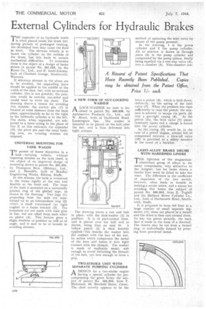
A NEW FORM OF NUT-LOCKING WASHER
ALOCK-WASHER for nuts is disclosed in patent No. 560,898, by Automotive Products Co., Ltd., and W. Brock, both. of Tachbrook Road, Leamington Spa. The washer is intended to he placed on the bolt after the nut, and is then deformed into tight .contact..
The drawing shows a nut and bolt in place. with the lOck-washer .(1) in position. It is of part:conical form, and is placed over the bolt end as shown, being then an easy fit. A hollow punch (2) is then forcibly applied; 'this knocks the washer into flat contact with the face of the nut, an action which compresses the metal of the bore and forces it into tight contact with the threads. The washer is made of malleable metal, soft enough to avoid distorting the threads of the bolt, yet firm enough to form a grip.
TWO-STROKE UNIT WITH SEPARATE PUMPING CYLINDER
A DESIGN for a two-stroke engine 2-t having a special cylinder for precompressing the gases forms the subject of patent No. 560,303, from T. Nicholson, 33, Newfield Drive, Crewe. The chief novelty appears to be the
method of operating the inlet valve by means of the pump pressure.
In the drawing, 1 is the powei cylinder ind 2 the pump cylinder. Air or mixture is drawn in through ports (3) in the pump cylinder _and compressed by the pump piston, finally being expelled via a one-way valve (4), into a chamber (5). This chamber con
tins a piston (6), which is held down, indirectly, by the spring of the inlet valve (7). When the pressure has risen sufficiently to raise the piston', the mixture is allowed to escape via ports (8) intO a gas-tight casing (9). As the piston lifts, the inlet valve (7) simultaneously opens and a charge is forced into the power cylinder,
As, the casing (9) would_ be, in the case of a petrol engine, always full of compressed mixture, a blow-off valve (10) is provided as a safety measure
in the event of a backfire.
LIGHT-ALLOY BRAKE DRUMS WITH HARDENED LINERS
MHE lightness of the magnesium1 aluminium group of alloys is, for many components, very attractive to the designer, but for brake drums a border liner must be fitted to take the wear. The difference in the coefficient of expansion of the two metals, however, often leads to trouble in making? secure union, and a means for avoiding this forms the subject of patent No. 560,903, from E. Toghill and the Midland Motor Cylinder Co., Ltd., both of Dartmouth Road, Smethwick, Staffs. It is proposed to form the liner in a large number of small separate segments (1); these are placed in a mould and the drnm is then cast around them. To key the pieces securely, the back face is made in the form of a dovetail. The inserts may be cut from a turned ring, or individually formed by pressing from powdered metal.