


Novel Development of Torsion-bar Suspension
Page 60
If you've noticed an error in this article please click here to report it so we can fix it.
AVEHICLE cqnstructed to operate either with wheels or endless tracks, is disclosed in patent No. 505,774, by Oesterr. Saurer-VVerke A.G., Vienna, Austria. The novelty of the scheme is the ingenious means by which the suspension system is utilized for lifting the wheels clear of the road when the endless tracks are required.
The drawing shows the vehicle on its wheels; these are attached to the frame via parallelogram linkages (2) which act as the suspension system, the resilient members being torsion bars (I) lying parallel with the frame. The inner ends of all the torsion bars are linked to an engine-driven tensioning gear, so that, by relieving the stresses, the vehicle sinks on to its tracks (3), after which the wheels are hoisted well clear of the road in an upward and inward direction.
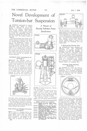
Unorthodox Valve Arrangements for Oil Engines.
PATENT No. 505,467, from A. Buchi, of Winterthur, Switzerland, discloses a novel scheme for the arrangement of the valves in an oil engine. Referring to the drawing, it will be seen that the two valves are co-axial, one (1) being of substantially normal design, whilst the other (2) is formed as a sliding sleeve with an external seating for itself, and carrying an internal seating for the Central valve, The outer valve controls the air charge and the inner one the exhaust, although their roles may be reversed if desired.
The advantages claimed are economy of space and excellent scavenging, the latter being demonstrated by the arrows which indicate the air flow.
Swiss Practice in Charging Two-stroke Oil Engines.
TWO types of charging blower for oil engines are available—the highspeed Roots types, and the slower piston compressor. An example of the latest practice in the design of the latter type is shown in patent No.
A42 505,888, by Sulzer Freres S.A. Winterthur, Switzerland.
In this design, the speed of the compressor piston is much slower than usual even with this type of pump, and, in spite of the large diameter, the unit should be extremely durable.
The drawing shows a two-stroke engine with the pumps mounted along
side the cylinders. Each pump has an upper piston (1} and a lower (4), both being mounted on the central rod. The rod is oscillated at a reduced speed by a lever (5) attached to the main piston rod. Air enters via a passage (2) and, after passing suction and delivery valves, reaches space 3 where it is stored ready for discharge into the engine inlet.
A Hard-wearing Steering Joint.
ASPHERICAL joint, designed for hard wear, and particularly applicable to steering tie-rods, is described in patent No. 505,869, by the Baker Axle Co., Cleveland, Ohio, U.S.A. This joint comprises a central stub which contacts, via a ball-bearing ring (2), with a hemispherical shell (3). These two components are bedded home by a powerful spring housed in a pressed-in cap. A spring-loaded sliding washer (1) excludes dirt.
Automatic Brake-adjusting Mechanism.
ASCHEME by which the shoe-tomm clearance is automatically maintained at a constant minimum, forms the subject of patent No. 505,795 from E. Trachsel and W. Huessy, Aa.burg, Switzerland.
The drawing shows a two-shoe brake operated by a dual-piston hydraulic cylinder of normal design. The shoes are retracted by a spring, the closed position being determined by a pair of screwed compression bars (1). These are linked by bell-cranks to exert outward pressure on a hard-faced sliding pin (3). This acts as a " feeler " and touches the drum at the same moment as the shoes. When facing wear occurs, the feeler contacts first, and this renders the linkages immovable; the shoes, however, are forcibly opened, resulting in the screwed rods (1) springing open the split sleeves (2) and so increasing their length by one thread pitch.