


IMPROVEMENTS IN SPEED-REDUCTION GEAR.
Page 46
If you've noticed an error in this article please click here to report it so we can fix it.
A Résumé of Recently Published Patent Specifications.
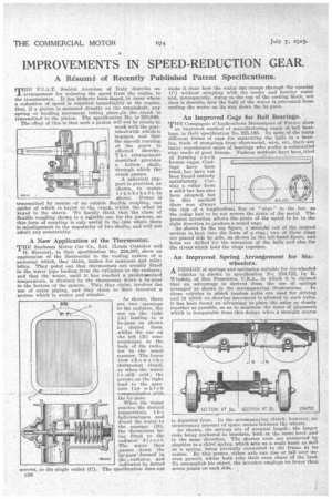
'I.A.T. Societe Anonima of Italy describe an
arrangement for reducing the speed from the engine. to the transmission. It has hitherto been found, in eases where a reduction of arseed is required immediately at the engine, that, if a pinion is mounted directly on the crankshaft, any spring or bending movement taking place in the crank is
transmitted to the pinion. The specification No. is 220,946.
The effe■A of this is that such a pinion will not be evenly in mesh with the gearwheel with which it engages, and that the smooth running of the gears is affected thereby. T h e arrangement described provides a hollow shaft, through which the crank passes. A spherical sup port is provided, as shown, to centre crankshaft in
sleeve. Power is transmitted by means of an outside flexible coupling, one spider of which is keyed to the crank, whilst the other is keyed to the sleeve. We hardly think that the class of flexible coupling shown is a saitable one for the purpose, as this form of coupling is only useful in the ell-se where there is misalignment in the angularity of two shafts, and will not admit any eccentricity.
A New Application of the Thermostat.
THE Sunbeam Motor Car Co., Ltd. (Louis Coatalen and 'H. Stevens), in their specification No. 234,307, show an application of the thermostat to the cooling system of a motorcar which, they claim, makes for neatness and reliability. They point out that thermostats are usually fitted in the water pipe leading from the cylinders to the radiator, and that the water, until it has reached a predeteamined temperature, is diverted by the thermostat down a by-pass to the bottom of the system. This, th,ey claim, involves the use of extra piping, and they claim to have invented a system which is neater and simpler.
As shown, there are two openings to the radiator, the one on the right (A) leading to a by-pass as shown in dotted lines, whilst the one oa the left (B) communicates to the bedy of the radiator in the usual manner. The lower view shows the thermostat closed, as when the water i s still cold ; the arrows on the right lead to the aperture (A4 which eommunieates „with, the by-pass. When the water reaches the desired temperature t h e bellowsasopen and divert the water to the passage (B), the thermostat be-. ing fitted to the radiator direc t. The water then passes down the by-pass, formed in the .radiator, and indicated by dotted The specification does not
make it clear how the water can escape through the opening (C) without mingling with the cooler and heavier water and, consequently, rising to the top of the cooling block, nor does it describe how the bulk of the water is prevented from cooling the water on its way down the by-pass.
An Improved Cage for Ball Bearings.
THE Compagnie d'Applications Mecaniques of France show an improved, method of manufacturing cages of ball bearings, in their specification No. 225,195. In spite of the many different forms of cage for separating the balls in a hearing, made of stampings from sheet-metal, wire, etc., there are many expeniensed users of beatings who prefer a substantial cage made of good bronze. Various methods have been,tried of forming such bronze cages. Castings have been tried, but have not been found entirely satisfactory.Cutting a collar from a solid bar has also been adopted, but in this method there was always the risk of a longitudinal flay or " pipe " in the collar had to he -cut across the grain Of the present invention allows the grain of the metal right direction to produce a sound cage.
As shown in the top figure, a straight rod of the desired section is bent into the form of a ring; two of these rings are placed side by side, as shown in the left-hand figure, and holes are drilled for the reception of the balls and also for the rivet d which hold the rings together. the bar, as metal. The to be in the
An Improved Spring Arrangement for Six.; wheelers.
Is departed from. In the accompanying sketch, however; an unnecessary amount of space occurs between the wheels.
As shown, the springs are of unequal length; the longer ends being anchored to brackets, both at the same level and in the same direction. The shorter ends are connected by shackles to a third spring, which stets as a scale beam as well as a spring, being pivotally connected to the frame at its centre. By this means, either axle can rise or fall over uneven ground, whilst both take their even share of the load. To accomplish his object, the inventor employs no fewer than seven joints oneaeh side.
A DESIGN of springs and springing suitable for six-wheeled
vehicles is shown in specification No; 234,722, by E. Winship, of San FrtillICIP.CO, U.S.A., in which it is claimed that an advantage is derived from the use of springs arranged as shown in the accompanyirw illustrations. In those vehicles in which tandem axles are used for driving and in which no steering movement is allowed in such axles, it has been found an advantage to place the axles as closely together as possible, so as to minimize the error if alignment :which is inseparable from this design when a straight course