


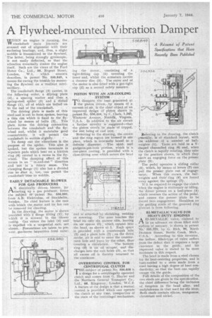
A Flywheel-mounted Vibration Damper W HEN an engine is running, the
Page 36
If you've noticed an error in this article please click here to report it so we can fix it.
crankshaft main journals are stressed out of alignment with their enclosing bearings, and, thus, a slight wobble is transmitted to the flywheel. The latter, being strongly gyroscopic, is not easily deflected, so that the vibration eventually shakes the engine itself. Such are the views of the Ford Motor Co., Ltd., 88, Regent Street, London, W.1, which concern describes, in patent No. 556,849, a means for curing the trouble by mounting the flywheel on a resilient intermediary.
The crankshaft flange (3) carries, in the following order, a elrisiing. plate (4), a spacing washer and then a. spring-steel spider (5) and a dished flange (1), all of which are bolted on
to the end of the crankshaft. _ The driving plate is made of. thin steel midis cut to form spokes,-leaving a thin rim which is fixed to the fly
wheel, by means of bolts This plate forms the driving connection between the crankshaft and the
wheel and, whilst it maintains good. concentricity, it will permit the crankshaft to wobble slightly. • ' To damp out the vibrations is the purpose of the spider. This also is spoked, hut the spokes terminate in separate pads which bear on a friction ring .(6) carried in a recess in the flywheel. The damping effect of this occurs in an " in-and-out" direction and not in 'a rotary sense. The clamping flange (1) also has a divided rim so that it, too, can perinit the crankshaft'boss to wobble.
EASILY DETACHABLE BLOWER FOR GAS PRODUCERS
AN electrically, driven blower, for starting, up a gas. producei-, forms the subject sSf patent No. 556,960. from A.B. Elektrolux, of StockhOlm. Sweden. ' Its chief feature is the ease with-which the motor and its fan can be removed for cleaning.
In the drawing, the motor is shown provided With a flange fitting (1); by which it is screwed -th the blower casing. Gas enters the inlet (4) and is expelled 'via a tangential .exit, not, -shoWn.. Precautions are taken to pre-vent .gas-borne-impurities -frorti enter 'nue. the motor,, consisting of a
• tight-fitting cap (5) covering the inner end, whilst the armature carries a thrower disc (3). The outer end of the motor is also fitted with a gas-tight cap (2) as a second safety measure.
PISTON WITH ANAIR-COOLING. SYSTEM T CI) dissipate the heat generated at
• the pia-ton crown: by means of a
Referring to the drawing, the crown and the ring region are formed in otie piece, which is-. internally bored to a definite diameter. The skirt . and gudgeon-pin-boss portion, which is a one-piece casting, is provided with a close-fitting nose which enters the head
and is attached--by shrinking, welding or screwing. The nose touches the head On only six narrow -ribs, leaving six air spaces (5); which extend into the head,. as „shown at 1.EAch space
is -provided with a countersunk hhle (2) and a plain hole (3) ; on the down
stroke, air is said to enter the countersunk hole and leave by the.othere thus Creating a circulation. The' bottom ring (4) is an oil straper, -.and -dis:charges into the exit. holes (3), so that all excess oil is thereby returned to
the crankcase. • OVERRIDING CONTROL FOR CENTRIFUGAL CLUTCH
THE subject of patent No 556,838 is a-design for a centrifugally operated clutch and comes from G. Hayter and the Northern General Transport Co., Ltd., 88, Kingsway, London, WC.2.. A feature of the design is that a manual control is provided which canoperate the clutch at any time', irrespective of the state of the -centrifugal mechanism. Referring to the drawing, the clutch generally, is of gtandard layout, with the :addition .01 a -number of ballweights (1). These are held in a Vshaped channelled ring (6) and, when the clutch is rapidly rotating, they take up the position shown, in which they exert an engaging force on the presser plate (2).
The pedal operates a sliding collar (5), which, by means of levers (7) can . pull the presser plate out of engagement. When this occurs, the ballweights and their' ring (6) are forced away against the springs (3).
If it be required to engage the clutch 'when the engine is stationary or idling, the 4river presses on a heel-piece (4) which reverses the action of the pedal, and causes the presser plate to be forced into engagement. Shoulders on the guiding studs of the grooved ring prevent it from followiug.
BI-METALLIC VALVE FOR • HEAVY-DUTY ENGINES
A HI-METALLIC valve, claimed to be an advance on those filled with sodium or mercury, is shown in patent No.' 555,378, by G. Rich, 96, North Division Street, Battle Creek, Mich., ' According to this inventor, the hollow, filled-type of valve suffers from the defect that it-requires a large clearance in the guide, and his improved valve is stated to be more moderate in this respect.
The-head is made from a steel chosen for itC heat-resisting properties, and is butt-welded to a stem made from a steel having a high degree of heat conductivity, so that the heat can rapidly escape via the guide.
Full details of the composition of the two steels are given in the specification. the chief difference 'being the inclusion of tungsten in the head alloy, and molybdenum in that Used for the stem. Bothsteels contain silicon, manganese, chromium and nickel.