


ACCESSIBILITY
Page 68
If you've noticed an error in this article please click here to report it so we can fix it.
in Forward-control Vehicles A Resume of Recently Published Patent Specifications TIIE invention described in specification No. 322,359, by the Wean Motor and Engineering Co. (1906), Ltd., and Joseph Sutton, is intended to provide a means whereby access. to the engine and surrounding parts of Vehicles can be made easier than with existing constructions.
The arrangement also enables a power unit to be .removed more easily, and should be particularly Useful in the case of _vehicles in which the driver is situated by the side of or above the engine.
The specification points out that with the large mudguards now in use with pneumatic tyres it is often very difficult to attend to or inspect certain parts, so this invention is intended to provide a means whereby the mudguard and part of thc,. floorboards can be readily swung sideways on the pivot shown in the two views. A bolt is provided to lock the mudguard in place for normal conditions.
A New Spring Suspension by Fiat.
SPECIFICATION No. 319,338, by Fiat Societa• Anonima, of Turin, lelates to a device which is claimed io reduce or prevent steering-wheel "
wobble" or "shimmy." It points out that if two separate spring suspensions are provided, one for the heavier stresses and one for the lighter stresses, -with two different periods of oscillation,
one will act as a shock absorber to the other. • In the arrangement which forms the subject of the present invention the front axle is supported by springs in the usual manner; besides these; however, is a spring lying parallel to the front axle, and engaging n a shackle at the lower end of • the sliding pivot pin. The shackle is shown, more plainly in the upper view. In some instances a helical spring may take the place of the auxiliary spring;
material, such as metal wool, and is provided at one end with holes through which air can enter, and at the other end with a fitting to .receive a flexible metal tube. At the 'free .end of this tube there is a connection which man be easily attached to the air inlet of a carburetter, so that air entering the engine must pass through the chamber.
The specification describes the method of starting as follows :----The chamber is heated by holding it over a. flame such as a gas-ring or by any other convenient _means ; the engine is the i started in the usual manner, all air entering the cylinder being heated by its passage through the device, thus enabling it instantly to volatilize the fuel. After the engine has started the tube can be disconnected from' the carburetter and the device removed.
The small figure shown on the right represents an adapter to enable the device to be connected to carburetters of different dimensions.
A -Combustion Chamber which Can Be Completely Machined.
POSSIBILITIES regarding the machining of combustion chambers and their form when produced have for some time been attracting the attention of designers. The plan described in specification No. 322,335, by Morris Motors (1920), Ltd., F. G. Woollard and A. G. Pendrell, is to form the consbustien chamber. so that all surfaces are curved, and to provide a means whereby machining operations can be carried out in a manner suitable to the requirements of large-scale production.
The chamber is formed partly in the cylinder block and partly in the head. The sectional view on the left shows the form of combustion chamber described, and the portion hatched with broken lines denotes that part which is operated upon by a milling cutter. The sectional view on the right shows the path of the cutter while operating. The lower views show the form of the chamber in plan.
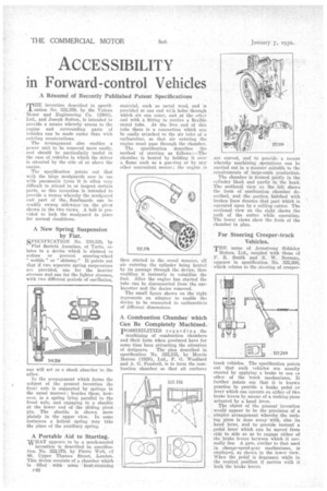
For Steering Creeper-track Vehicles.
TEE name of Armstrong Siddeley Motors, Ltd., coupled with those of P. R. Smith and S. W. Norman, appears in specification No. 322,269, which relates to the steering of creeper track vehicles. The specification points Out that such vehicles are usually steered by applying a brake to one or other of the track mechanisms. It further points out that it is known practice to provide a brake pedal or lever which can operate on either of Vivo brake levers by means of a rocking piece actuated by a hand lever.
The object of the present invention would appear to be the provision of a .simpler arrangement whereby the rocking piece is done away with, also its hand lever, and to provide instead a pedal lever which can be moved from side to side so as to engage either of the brake levers between which it normally lies. A gate, similar to that used in change-speed-gear mechanisms, is employed, as shown in the lower view., When the pedal is depressed while in the central, position it carries with it both the brake levers.