


An Improved Shape of Gear Tooth
Page 86
If you've noticed an error in this article please click here to report it so we can fix it.
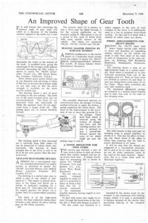
IT is well known that increasing the I pressure angle of gear teeth will result in a decrease of the bending moment applied to the teeth, but it also diminishes the radius at the bottom of the teeth. A modified form, giving the advantages of the stronger tooth without seriously decreasing the fillet radius, is shown in patent No. 760,091 (Caterpillar Tractor Co., 800 Davis Street, San Leandro, California, U.S.A.).
Most vehicle gears nearly always run in one direction and advantage is taken of this fact to increase the pressure angle on one side only, so that the extra strength is available on the more heavily loaded side.
The drawing shows a pair of gears according to the new scheme. The teeth are of the usual involute form, but are non-symmetrical. The faces (1) are generated from one base-circle (2) whilst the opposite faces (3) are generated from a larger circle (4). The mating gears are, of course, similarly formed.
The working depth is thus increased yet a relatively large fillet radius (5) can be preserved to reduce stress concentration. The increase in beam strength due to the form is said to be 30 to 40 per cent, greater than the standard form.
LEYLAND BUS-CHASSIS DETAILS
A, DESIGN for a rear-engined vehi
cle, intended particularly for public service, is disclosed in patent No. 759,760. (Leyland Motors, Ltd., Suffolk House, Laurence Pountney Hill, London, E.C.4.)
The drawing is a partial plan view in which a pair of rear wheels is indicated at I. The engine is placed crossways in the frame and drives via a clutch, or hydraulic coupling (2), a bevel gear (3). This takes the drive to the angled gearbox (4) thence via a cardan shaft to a crown-wheel assembly (5).
The latter is of the high-speed variety, the final reduction taking place between a spur pinion (6) and a mating gear on the wheel assembly.
a34 The primary shaft (7) is tubular so that a drive may be taken through it for the various auxiliaries, as, for example, pulley 8. This patent is one of a group of five, each of which deals with some specific feature of the vehicle. The others are numbered 759,761, 759,762, 759,763 and 759,764.
SEALING MASTER PISTONS BY SURFACE TENSION
A SIMPLE modification to the master piston of a hydraulic brake system forms the subject of patent No. 760,157 (chafer lndustriegesellschaft Schweinfurt m.b.H., 30 Georg Schafer Street. Schweinfurt, Germany).
The assembly illustrated operates on conventional lines, the plunger (1) being pushed leftwards to apply the brakes, a spring supplying the return force. The basis of the improvement is the provision of one or more fine grooves (2) in the plunger. These hold fluid which is smeared along the surface of plunger and bore, and the resulting surface tension is claimed to give a second-line defence against the entry of air which might get past the sealing rings (3 and 4).
A STONE DEFLECTOR FOR TWIN TYRES •
THE narrow gap between a pair of twin tyres is prone to pick up stones which then remain wedged and can set A simple attachthis is shown in
up severe local wear. ment for preventing patent No. 759,048 (Firestone Tyre and Rubber Co., Ltd., Great West Road, Brentford).
The two rims are usually clamped together by studs (1) and it is proposed to place on them a thin steel disc (2). It extends outwardly to the maximum possible diameter having regard to tyre deflection.
To deal with stones that might try to enter through the hand-holes in the rim, the disc is fitted with flanges at point 3.
The disc could also function as a safety support in the case of total collapse of the tyres; it is additionally used as a fan to promote brake-drum cooling. To this end it is fitted with a number of radial vanes, not shown.
WHEEL ARRANGEMENTS FOR HEAVY BOGIES PATENT "No. 759,755 deals with
heavy bogies having eight wheels or more and describes an equalizing scheme whereby all the wheels are made to take their share of the load, in spite of inequalities in the road surface., (A. Ronning, 5030 Woodlawn Boulevard, Minneapolis, Minnesota, U.S.A.)
The drawing shows a plan of an eight-wheeled bogie as a typical example. Each wheel is mounted on its own stub-axle projecting from one of the swinging arms (1). Pairs of these arms arc pivoted in carriers (2) and these in turn can swing about cross-tubes (3) on the frame. These tubes constitute the only axle members used.
The laminated sAspension springs are attached to a median frame bracket and at their free ends to the ends of the swinging arms.
The chief feature is that each pair of swinging arms is geared together, as shown at 4. This has the effect of forcing one wheel down if the other is lifted, thus ensuring that the load is evenly distributed at all times.
It will be seen that the wheels are staggered in a fore-and-aft direction; this is said to be of .value because they do not all strike expansion joints in the road at the same moment. Apparently this is a virtue when used on American highways.
Included in the claims made by the inventor is one concerned with braking torque, which, it is said, is maintained in balance between all the wheels, thus preventing kick-up of the rearmost wheels.