


AN ENGINE ON A NEW PRINCIPLE.
Page 74
If you've noticed an error in this article please click here to report it so we can fix it.
Tw°pistons working in the same cylinder is by no means a new idea, but previous efforts in this ,direction have mainly been directed towards the reduction of vibration. In the case of the present invention, however, the effort is in the direction of producing a more perfect cycle of operations. The Invention is described in specification No. 252,135, of M. A. S. de Laforcade, of Lamotte-Beuvron, France.
The objects are to produce an engine in which it is possible to obtain the advantages of supercharging without necessarily increasing the ratio of compression to a corresponding extent, the economical utilization of the energy developed during the explosion by employing a suitable ratio of expansion which is independent of the ratio of compression and the consequent lowering of the temperature at the end of the firing stroke.
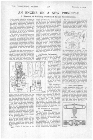
It will be seen that the engine has two crankshafts, one below and one above— the upper one revolving at half-engine speed. Ports for inlet and exhaust are provided in the centre of the cylinder find a projection from the piston, which does not come into contact with the walls of the cylinder, is provided on either lower or upper piston for thepurpose of occupying space so that suitable compression can be obtained without the rings passing the ports. Gearing connects the upper and lower crankshafts, and the valves are operated by means of cams on the upper crankshaft.
The upper left-hand view is an end sectional one. whilst the lower righthand view is a diagrammatical explanation of the movements of the pistons. The upper right-hand view is a graph indicating the movements of the two pistons, in which the dotted-line curves represent the pistons, and the full-line curve represents the varying_ volume of the working chamber.
I is the complete expansion volume ; II is the total suction volume ; III the stroke of the driving piston ; IV the stroke of the expansion piston ; A the admission stage; E the exhaust stage ; 0 the compression stage and D the expansion stage.
These comprise all the stages of the 1148
engine embodying the cycle used, and enable the ratio of the strokes adopted for the driving and expansion pistons to be varied for the purpose of obtaining-selected proportions for the admiss sion space and the expansion space. On examining the independent operation of each of the pistons it will be seen that the driving piston works on the four-stroke cycle in the usual order (suction, compression, expansion, exhaust), whereas the expansion piston works on the two-stroke cycle, so that during the up-stroke it embodies the two stages, compression and expansion (with explosion at half stroke) and during the down-stroke the two stages, ex: haust and suction. During the relative movement of the two opposed pistons everything occurs as though the expansion piston constitutes the movable head of the cylinder, diverging during the stages of compression and expansion, and converging during the stages of exhaust and suction.
A Simple Carburetter. A FoRm of carburetter in which no jet is employed, is shown in the specification of W. A. E. Crombie, No. 260,820, in which an ordinary float chamber delivers petrol to a chamber. at the lower end of the carburetter. A vertical tube is employed for the admission of air, which travels in a downward direction where it meets a perforated or gauze diaphragm through which the petrol gas can rise and mingle with the air as it is drawn upwards to the engine.
T h e specification mentions the fact that the tube through which the air enters is adjustable, so that the gap between its lower end and the diaphragm can be adjusted by means of a screw, and a fine adjustment can be made while running by means of a helical slot. The specification describes the sides of the mixing chamber as being lined with gauze or similar absorbent material, and refers to an adjusting screw by which the relative height of the diaphragm with the petrol level can be varied.
To Counteract Torsional Vibrations.
IN Specification No. 247,911, the General Motors Research Corporation of Delaware, U.S.A., describes a device which, it claims, reduces torsional vibrations of revolving shafts such as crankshafts.
The example shown and described in the specification is a aix-eylindered crankshaft in which the device is shown fixed to the web of the crank situated midway between the centre bearing and the end farthest from the flywheel. The lower view shows the crankshaft looking from the front towards the rear —the counterbalance weight being removed for clearness. The web to which the device is attached is made with a flat face on one side to which a bracket is 'bolted, this carrying a hinge on which the counterbalance is pivoted. It consists of a weight having a pivot in its centre, and extending arms which bend backwards over the centre of the crank. A number of thin steel plates form springs which lie on both sides of the hinge, tending to keep the pivoted member in a central position, but pressure, if brought to bear on the hinged member, could cause it to swing on its pivot..
The wording of the specification is very vague, and mixes up the vibrations that occur through centrifugal force,. with those produced by torsion. It tells us that when an engine is running at a certain speed, the impulses are in step with the natural period of vibration of the crankshaft, consequently a periodic torsional vibration takes place, which is
will understood. It further tells us that the pivoted weight held in a central position by finely laminated lively springs will set up a period of vibration that will damp out or counterbalance the torsional vibration orthe crank, but how this is acoomplished is not. clear.
A New Valve Spring.
OHN MARSTON, LTD., and J. E.
Greenwood, in specification No. 259,870, show a new form of valve spring. The spring consists of what is described as a pair of " mousetrap " U-shaped springs, and the main object appears to be to provide a type of spring that can be readily replaced without disturbing the valve. The valve guide has two holes drilled through it to take the lower ends of the springs.