


AN EFFICIENT BRAKE SERVO.
Page 64
Page 65
If you've noticed an error in this article please click here to report it so we can fix it.
WE recently carried out a short test with the B-K Booster Vacuum Brake, as it is called. The actual model tested was fitted into a 2-ton chassis, of which we took charge in Bayswater Road, Hyde Park, and drove direct to the offices of this journal, traversing on our way Oxford Street and other congested thoroughfares during the early morning rush. This, as will readily be realized, gave us ample .opportunity for trying out the pedal-controlled brake, to which the B-K device was attached, on many occasions, and we found it extremely simple, powerful and very rapid in action, and it could be controlled to any degree of braking without difficulty.
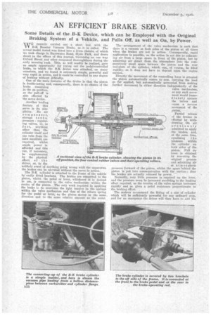
One of the main features of the device is that the piston is double-acting aid, consequently, there is no chance of the brake remaining in the on position, its the pull-off is also effected by the servo device.
Another leading feature of this servo is its simplicity. No air C ompressor, storage tank s, pressure regulating valves, or, in f a c t, anything other than the cylinder itself and one tube from the inlet manifold, are required, whilst ample power is afforded and this can, if necessary, be supplemented by • the physical effort of the driver, or, in the unlikely event of anything going wrong with the apparatus, the brakes can be operated without the servo in action.
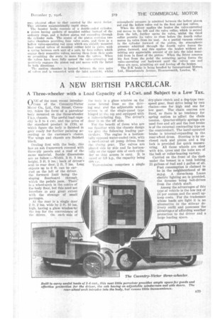
The B-K cylinder is attached to the frame of the vehicle by easily fitted brackets. The brakes are connected to the piston, whilst lhe pedal or lever, whichever it is desired to use, is connected to the valve mechanism within the centre of the piston. The only work required in applying the brake iz to overcome the light tension in the springs within the valve mechanism and that of the return spring for the pedal or lever, as the piston moves in the same direction and to the same relative amount as the neda .
PIPE 't•O MAN FOLp
6Tr1o.1PHEmc JNLET PASSAGE. CONNECT PEDAL ROO
The arrangement of the valve mechanism is such that there is a vacuum at both sides of the piston at all times when the brakes are not in action. Consequently, rapid application is possible, as the action is not due to exhausting air from a large space in front of the piston, but by admitting air direct from the atmosphere into the comparatively small space between the piston and the rear end-plate of the cylinder, which can„ of course, be filled rapidly, as it does not have to depend upon the engine suction.
Directly the movement of the controlling lever is arrested the piston automatically comes to rest, carrying the load so far applied, but automatically prevented from making further movement in either direction independently of the valve mechanism, as any such movement would immediately operate the valves and came a reverse movement of the piston.
Partial release of the brakes is effected by withdrawing the air previously admitted to apply the brakes, and, at the same time, equalizing t he pressure within the cylinder on both aides of the piston. Pull release is obtainea by reversing the original process and admitting air at atmospheric Pressure forward of the piston, whilst the space behind the piston is put into communication with the suction ; thus the brakea are actually released by power. Normally, very little pressure is required on the lever, and the pressure must be increased according to the braking effort required, as the tension of the valve springs increases rapidly and so gives a pedal resistance proportionate to the braking effort.
The makers recommend the fitting of a size of cylinder which will be sufficiently powerful for any ordinary stop, and for an emergency the driver will then have to add his RETRACTING SII'RING. own physical effort to that exerted by the servo deviee. This obviates unintentionally rapid stops. The booster brake consists of a donble-ended eylinder, a piston having gaskets of moulded rubber instead of the ordinary rings, and a hollow piston rod extending through the cylinder ends. The centre of the piston contains two valve chambers providing four valve seats, and there is a hollow valve-operating rod upon which are slidably mounted four conical valves of moulded rubber. held in pairs, with a spring between each unit of a pair, by four collars which engage their respective valves, moving them from their seats or permitting the seats to move from the valves. When the valves have been fully opened the valve-actuating rod positively engages the piston rod and moves with the latter ill ladth directions.
TIE: suction chamber is located between the Iwo pairs of valves rind is connected with the inlet manif41. whilst
atmospheric pressure is admitted between the hollow piston rod and the hollow valve rod to the first and last valves.
When the driver applies the brakes the valve-operating rod moves to the left and the valve collar, which is second from the left, further opens its valve, whilst the third collar permits its valve to close before the fourth collar moves its valve from its seat. As a partial vacuum exists in the cylinder forward of the piston, the atmospheric pressure admitted through the fourth valve forces the piston forward, and this applies the brakes without admitting any appreciable amount of air into the inlet manifold from in front of the piston. When the driver removes his foot from the pedal the retracting spring forces the valve-operating rod backward until the valves one and three are open, admitting air and forcing off the brakes.
The B-K brake is, being handled by International 'Motors, Ltd., Bloemfontein Avenue, Ilammersmith, London, W.