


THORNYCROFTS DUCE A 3-TONNER.
Page 58

Page 59
Page 60
Page 61
If you've noticed an error in this article please click here to report it so we can fix it.
An Entirely New Goods Chassis with a N ely Low Platform Level and with a Capacity t-day Demands.
WITH all the infinite variety in weights and sizes of loads users seem to group themselves more definitely than one would have thought possible into, for example, the 1-ton, the 2-ton or the 3-ton class, and so on by tons up to 6 tons, after which they step lip by 2-ton stages. They do not seem to care for any intermediate stages, such as the 21-tonner, whilst (to emphasize our point) no maker would dream of catalog-ning a 3i-tanner There has, for this reason, been an important modification in the range of Thornycroft chassis, the old 21-tonner, known as the B.X. model, having been dropped and its place taken by the A2 and the K.B. models. The A2 model is a 2-tanner having the FB4 engine and unit employed on the Al 30-cwt. model, but having a stronger axle to deal with a 2-ton net load. The six-wheeler has two of these 2-ton axles. The K.B. model now to be described is a 3-tonner and is a development of the line of thought which produced the LB. low-level passenger chassis in April last (see The Commercial Motor for April 13th, 1926) and which, we are sure, is destined to carry the lineage still further.
The new range of models emanating from Basingstoke are based upon a design of power unit which embraces engine, clutch and gearbox in unit form, the pain ideas being economy in first cost and in runping and maintenance. There are arguments in favour of the use of a gearbox separate from the engine, the chief ones being accessibility of the clutch and the ease' of removing the gearbox from the chassis. As against this there is always the problem of ensuring alignment between the engine and gearbox, and it is general practice to provide universal joints on the shaft connecting them, and first cost is usually higher. It is claimed by the protagonists of the unit system of combining three of the chief components that production is cheaper, that with large inspection doors every moving part can be kept under observation, that alignment Is absolutely ensured and is always maintained, whilst It is quite easy to remove the unit complete when a serious overhaul is needed and to take it to a bench where the job can be done properly. At the same time it is easy to remove the gearbox alone, and it does not take long to take away the gearbox and to expose the whole of the clutch gear. The first of these complete Thornycroft power units was the FB4, rated at 22.5 h.p. on the R.A.C. formula and developing 35 b.h.p. at 1,500 r.p.m. (the crankshaft speed at which, all rhornycroft engines are rated). The cylinder bore of that engine is 31 ins, and the piston stroke is 5 ins. which has been adopted for the new K.B. 3-ton goods chassis, and it will be useful to intending purchasers to recall some of its salient features, for it was fully described when we dealt with the L.B. chassis.
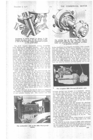
The cylinder bore is 44 ins, and the piston stroke 5i ins., and could develop as much as 55 b.h.p. at a rate of revolution in excess of the 1,500 r.p.m. at which it is rated. The four cylinders are cast monobloc, with ample water spaces and a detachable head, and cleanliness of exterior has been one of the aims of the designers, an example being found in the excision of the nuts and studs holding the cylinder casting to the upper half of the crankcase. The studs are inserted into bosses in the casting and the nuts are inside the crankcase—a simple change, but one which assists in keeping an engine exterior clean. The inlet and exhaust manifolds are held by two double dogs, the valves are instantly accessible and the tappets are adjustable. -The crankshaft is carried in three die-cast white-metal bearings of good length. Duralumin connecting rods and aluminium pistons with floating gudgeon pins are used. The lubricating oil is force-fed to the main bearings and crankshaft bearings and through the drilled crankshaft to the big-end bearings. A test cock, a drain plug, a dip stick and an oil-pressure gauge enable the driver to maintain correct oil level.
A propeller-type pump and a fan are mounted at the front of the engine, and the water can circulate therm°. siphonically should the pump fail, the pipes being of ample diameter. The Zenith carburetter is disposed on the off side, and in the intake passage is a second butterfly throttle, which is automatically controlled by the engine speed, the governor mounted at the forward end of the camshaft being quite new in design. Centrifugal force is still employed, but not to control revolving weights on lever arms. Bolted to the timing wheel on the camshaft is a plate having six radial slots. A ball in, in diameter is inserted in each of these slots, two balls being sufficient for a fast-running engine and as many as six for slow-running engines. In the 11B4 engine three of the slots have a ball each. These balls are thrown out and, therefore, exert a pressure in relation to engine speed and, bearing against a flat plate on one side, on the other they force forward a coned plate, a coil spring resisting this action of the balls. On the coned plate is a sleeve having a rack cut on its end to engage with a gearwheel. The sleeve has a total travel of about half an inch and, therefore, it only causes. the gearwheel to oscillate to the extent of a few teeth. To the wheel shaft is attached a wire, which is twisted in a tube leading to the carburetter, the oilier end of the
wire being attached to the stem of the butterfly throttle. The wire is thus twisted more or less according to the engine speed, and closes and opens the master throttle. The driver's accelerator pedal operates another throttle, but excessive engine speed is checked by the master throttle.
Careful driving on the K.B. chassis under full load gives from 9 to 9i miles to the gallon of fuel.
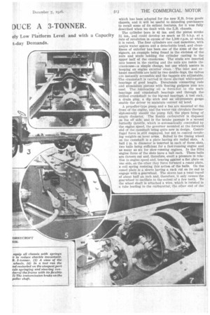
The power unit is supported at three points on the chas.sis ; at the front it is held in a trunnion, which is carried on a rubber block held by a stirrup of invertedV shape; at the rear it is bolted rigidly to two brackets. Anyone who has witnessed the racking strains to which the War Department subjects the six-wheelers would admit the efficacy of this mode of suspension.
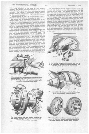
The single dry-plate clutch with asbestos fabric surfaces has very light rotating parts, and gear changes, as we noted on a test run, are remarkably easy. The four gear ratios are 5.12 to 1, 2.75 to 1, 1.56 to 1 and 1 to 1, whilst on the reverse the ratio is 7.68 to 1, the final-drive ratio being 7.25 to 1. The power is taken through an intermediate propeller shaft with a fabric universal joint in front and supported in a ball bearing, which, again, is mounted in a fabric disc bolted at three points to the second cross-member of the frame. Behind this Is the Spicer joint connecting to the hollow propeller shaft, transmitting the power to the worm shaft over the back axle. The transmission brake is an external-contracting band, which virtually completely encircles the drum, can be accurately adjusted by screwing in or out a single stud and is operated by a simple pinching action as described by us in April last. The final drive is by an overhead worm shaft and through side shafts from the differential gear and dog clutches to the hubs. The wheels are bolted to the hubs and can be removed without disturbing the hub bearings, and the side shafts can be withdrastu without the need for jacking up the axle. The wheels are of new design, being cast with eight webbed spokes and deeply dished. The front wheels are cast with webbed spokes with an inward curve, this form -being adopted for the sake of symmetry. In their case, too, they can be removed from the hubs without the bearings being disturbed. They are mounted on tapered roller bearings, and the stub axles are alike, so that in the case of a vehicle ordered for overseas it is easy to fit left-hand steering. The tyre size is 36 ins, diameter for 30-in. by 5-in, rims, singles in front and twins at the rear.
The K.B. chassis •represents certain deviations from Thornycroft standard practice. Thus one observes that the track rod between the front wheels is ' placed behindthe axle, as was first done on the LB. chassis. This is. done in order to give better steering centres. The steering gearbox is bolted outside of the frame and a complete worm wheel is provided for engagement with the worm on the steering column. The position enables the driver to be placed more to the right, whilst the forni of gear gives four wearing areas to the worm wheel. The driver being placed over to the right, the brake lever iS not mounted on the gearbox casing beside the gear-change lever, but the quadrant is mounted on the frame.. We do not approve of lefthand brake operation, because the left arm is the best steering arm and the right arm and side are the stronger for brake application.
Road springs that are flat (or approNiniately so) under load are a feature of all Thornycroft chassis. The front springs are 48 ins, long, the leaves being 3 ins, wide and * in. thick. The rear springs tire 60 ins.
long and -4 ins. wide and in. thicker than the front springs; They are, therefore, 'exceptional in their dimensions, and, in the case of the rear springs, lugs on the axle bracket and ears on the top leaves ensure that they shall always be in true alignment; the head of the spring centre bolt is thus not relied upon for locating the spring. The shackle pins are all held in split and bolted jaws, which give a firmer holding of
the shackle pins. • We were afforded, on the day on which we inspected the chassis, an opportunity to put; a fully loaded chassis to any suitable running test. The weather was true
to. thetraditions of an English November, with a steady rain and sufficient fog to reduce visibility to about a hundred yards. We chose a short route of a few miles from Basingstoke, which took us over Farleigh Hill. The vehicle maintained a highly creditable turn of speed and took the hal with such consummate ease that one found it no test at all. In fact, we might not have been fully impressed but for the fact that another vehicle of apparently the same load capacity completed the long approach to the hill and struck the real rise with its radiator already boiling, and on the steepest portion was brought to a standstill. Before we left the hill, however, it had got going again, but the incident made us realize that-the test was no light one. The K.B. Thornycroft runs extremely well, is pleasantly quiet, the gears change easily, the brakes are good and the power ample, for with ease it pulled away again from the steepest part of the hill, where we had brought it to a dead stop. With a 36-in, wheel and fiat springs the platform level is brought lower than is usual for a lorry of the 3-ton capacity, the height of the frame above the ground being only 2 ft. 54 ins. The chassis weight is 2 tons 141 cwt., and the axle weights laden are : front 2 tons 2 cwt., rear 4 tons 81 cwt. The wheelbase is 13 ft., the track at front 6 ft. 31 ins. and at rear 5 ft. 11 ins., whilst the body space from dash to rear of frame is 15 ft. 111 ins, and the overhang 5 ft. 61 ins. The ground clearance is 10 ins.
The frame is amply strong, being formed of pressed steel of channel section 7 ins, deep and 4 ins, wide in the flanges. The price of the K.B. chassis is £650, with additions for electric lighting and starting set and for a mechanical tyre pump for use when pneumatic tyres are fitted. The chassis is supplied with a full equipment.