


Patents Completed.
Page 20
If you've noticed an error in this article please click here to report it so we can fix it.
Complete specifications of the following patents will be sent to any address in the United Kingdom upon receipt of eightpence per copy at the Sale Branch, Patent Office, Holborn, W.C. ;
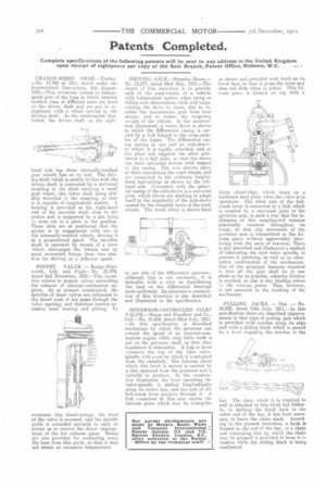
CHANGE-SPEED GEAR—Fischer. —No. 17,790 of 1911, dated under the International Convention, 4th August, 1910.—This invention relates to changespeed gear of the type in which internal toothed rime of different sizes are fixed on the driven shaft and are put in engagement with a wheel carried by the driving shaft. In the construction illustrated, the driven shaft on the right
hand side has three internally-toothed gear wheels fast on its end. The driving shaft which is axially in line with the driven shaft is connected by a universal coupling to the shaft carrying a small gear wheel, this latter shaft being slidably mounted in the coupling, so that it is capable of longitudinal motion. A bearing is provided at the right-hand end of the movable shaft close to the pinion and is supported by a pin lying in slots cut in a plate in the gearbox. These slots are so positioned that the pillion is in engagement with one of the internally-toothed wheels, driving it. at a proportional speed. The movable shaft is operated by means of a lever which disengages the wheels and by axial movement brings them into post(ion for driving at a different speed.
POPPET VALVE. — Rudge-Whitworth, Ltd. and Pugh.—No. 25,474, dated 2nd November, 1910.—This invention relates to poppet valves controlling the exhaust of internal-combustion engines. As at present constructed, the spindles of these valves are subjected to the direct rush of hot gases through the valve opening, and therefore receive excessive local heating and pitting. To
overcome this disadvantage, the head of the valve is recessed, and the spindle guide is extended upwards to such an extent 94 to receive the direct impingement of the hot exhaust, gases. Means are also provided for conducting away the heat from this guide, so that it does not attain an excessive temperature. DRIVING AXLE.—Bramley-Moore.— No. 12,377, dated 23rd May, 1911.—The object of this invention is to provide each of the road-wheels of a vehicle with independent motion when rising or falling over obstructions while still transmitting the drive to them, also to insulate the transmission gear from road shocks, and to reduce the unsprung weight of the vehicle. In the construction illustrated, a worm drive is shown in which the differential casing is carried by a link hinged to the cross-member of the frame. The differential casing carries at one end an axle-sleeve, to which it is rigidly attached, and at the other end supports the other axlesleeve in a ball joint, so that the sleeve can have universal motion with respect tn the casing. The two sleeves carry at their extremities the road-wheels, and are connected to the ordinary longitudinal leaf-springs as shown on the lefthand side. Concentric with the spherical casing of the axle-sleeve is a universal joint, which allows the shafting to adapt itself to the angularity of the axle-sleeve caused by the irregular move of the roadwheels. The worm wheel is shown fixed
to one side of the differential gearcase ; although this is not necessary, it is desirable with a view to distributing the load on the differential bearings more uniformly. An alternative construction of this invention is also described and illustrated in the specification.
GOVERNOR-CONTROLLED INLET VALVE.—Moore and Shardlow and Co., Ltd.—No. 16,850, dated 22nd July, 1911. —In this specification is described mechanism by which the governor can control the speed of an internal-combustion engine while very little work is put on the governor itself, so that close regulation is obtainable. A link or lever connects the top of the inlet valvespindle with a rod by which it is actuated from the camshaft. The fulcrum about which this lever is moved is carried by a link operated from the governor and is variable in position. In the construction illustrated, the lever operating the valve-spindle is slotted longitudinally along its centre line, and one arm of the bell-crank lever projects through it. A link connected to this arm carries the fulcrum piece which may be triangular
as shown and provided with teeth on its lower face, so that it grips the lever and does not slide when in action. This fulcrum piece is formed on top with a
blunt chisel-edge, which bears on a hardened steel plate when the valve is in operation. The other arm of the bellcrank lever is connected to a link which is coupled by a universal joint to the governor arm, in such a way that the inclination of this coupling-rod remains practically constant throughout its range, so that any movement of the governor arm is transmitted to the fulcrum piece without appreciably interfering with the ratio of traverse. There is also described and illustrated a method of lubricating the inlet valve spindle, to prevent it jamming, as well as an alternative construction of the mechanism. One of the principal features required is that all the gear shall lie in one plane as far as possible, whereby friction is avoided, as also is any binding action i:1 the various joints. This, however, is not essential to the working of the mechanism, PULLING JACKS. — Day. — No. 16,332, dated 15th July, 1911,—In this specification there are described improvements in that type of pulling jack which is provided with notches along ita edge and with a sliding block which is moved by a lever engaging the notches in the
bar. The chain which it is required to pull is attached to this block but hitherto, in shifting the block back to the outer end of the bar, it has been necessary to leave the chain slack. According to the present invention, a hook, in formed in the end of the bar, or a chain and connecting link by which the chain may be gripped is provided to keep it in tension while the sliding block is being readjusted.