


road and workshop
Page 49
If you've noticed an error in this article please click here to report it so we can fix it.
)y Handyman
Benchwise: Lathe sense (25)
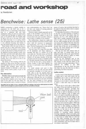
WHEN overhauling a vehicle, whether in ireparation for the MoT test or for a tormal service, it is annoying to find excess year in a spherical ball and bush onnbination when you have no spare parts o hand and the free play or chatter is too ;reat to be ignored. This can happen with he ball at the root of the gear lever itself, ind where the lever is in a casing remote rom the gearbox there are quite often one )1two spherical housings and bushes to ;arry the speed change rod to the main box.
These bushes will in the main be brass or nonze and due to their semi-rotary action he wear will not be uniform, so an attempt o take up the slack by letting the halves of he spherical housing together usually ends with slack and then quite tight places when )perated. Also the wear is not restricted to he ball but is also evident in the cup or lousing; thus a new ball on its own is not dways the answer.
The halves of the housing could be let :ogether by filing across the flats, and then and lapping the new very stiff combination ogether with grinding paste until the required freedom is obtained a slow task which always leaves grains of grit in the metal.
rhe alternative Therefore when no new parts are handy the only alternative seems to be to let the housing halves together and at least reduce some of the slack for the time being, for when approached, quite a number of turners
may understandably say: "Sorry, but I do not have any means of turning, spherical items in a centre lathe!"
However, quite a simple approach can be made to this problem: a rig can be set up allowing an accurate sphere or cup to be turned which will work smoothly without a trace of play or stiffness in any position.
The method here—based on a lathe tool that has permitted movement around a fixed pivot—calls for accuracy. in preparation and positioning, and a neat fit of working parts. The first requirement is a flat steel bar 2in. x lin, and roughly Ift long.
The next move is to clear the cross-slide of all equipment and them make-up a shoulder belt that is a perfect fit in the cross-slide slot. This bolt comes up from the slot and one end of the bar is accurately drilled to fit the plain shoulder of the bolt, and there must be no play or freedom in this fit. The plain shoulder finishes flush with the top of the flat bar and a spring tension or friction washer is then fitted between nut and bar; it is advisable to use a stiff self-grip type nut.
A small tubular tool post is then postioned on the bar; this tool post should be internally threaded in its lower area in order that it can be secured from the underside of the bar. Also the tool-carrying head of the post should have some radial adjustment, although this can be achieved by the bolt securing the tool post. If the flat bar has been arranged to have spanner clearance between it and the cross-slide, this means, of course, that provision has had to be made for the pivot bolt to have a spacer added beneath the bar.
To determine the position of the tool post on the bar, it is first necessary to mount a suitably sized ball in the chuck—this, for instance, can be a new steering ball pin. Then with a scriber mounted in the loose tool it is easy to move the tool post along the bar while swinging the bar on its pivot and tracing the outline of the ball. Once the post distance or position is established, the circular base of the post can be scribed on the bar, the circle centred and a fit hole drilled for the post lock bolt.
This rig can deal with various sizes of balls and cups, so several holes can be drilled in the bar with an kin, space between which will then permit a radius or sweep that will cover a range of sizes.
Now for the important part of the exercise: this is to be able to set the pivot bolt exactly in line with the centre of the work, both in cross and axial planes. This is achieved by drilling a lin• hole three-quarters of the way down the pivot bolt from the top; this hole has to take a good fitting rod with a true point.
Lathe centre A lathe centre is then fitted in the mandrel or chuck and a true work centre can be established; also it pays to mark the exact position of the cross-slide in case it is necessary to run it clear to mount the work; if there is slide limit stop, so much the better.
The test pin or rod is also a value in that the radius of the tool itself can be set for a given spherical diameter, provided that allowance is made for the radius of the pin itself, that is, half its diameter, or the top kin, of pin reduced to tin. in which case there is no need to remember an allowance.
A normal boring tool will suffice as the cuts will be fine, at a speed suitable to the material, whether brass or steel. The extra length of the pivot bar is used as a lever to swivel the tool round the sphere. While this has described the method for turning a ball, either new or after building up, almost the same rules apply for boring the spherical housings, as the tool, is set to the same cutting radius. Naturally, there can be a problem in mounting certain spherical housings, especially when in two,parts, and it may be necessary to use a four-jaw chuck, or even braze or solder them to a flat bar for face plate mounting, the main point being that another regular feature of vehicle parts reclamation can now be dealt with in an ordinary centre lathe.