


To Solve the Differential Problem
Page 25
If you've noticed an error in this article please click here to report it so we can fix it.
EFFORTS to solve satisfactorily the Liproblem of the differential gear continue, probably being stimulated by the requirements of military mechanization. Like most puzzles, the interest seems to grow with the difficulty, whilst the ingenuity displayed by inventors is considerable.
The problem, of course, is to avoid losing the drive altogether when it is lost by one wheel. Recently we described two ',notably clever a, mechanisms which, in different ways, achieved, to a greater or less degree, the desired end (" C.M.," January 2, 1942). Now a new patent has appeared, detailing a device functioning according to a third method.
In view of the hornets' nest we stirred up recently by criticizing another patent, we are a little chary of expressing an opinion .about this one, hut it has certain points with which we do not feel wholly satisfied.
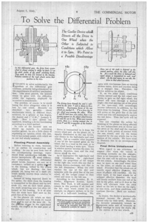
Floating Planet Assembly Before referring to them, however, le let us outline its construction and working. As can be seen from two of the accompanying drawings, reproduced from specification 545,688, the device incorporates the usual differential components. The differential planet bevels, ,however, are not, as is customary, carried on a spider seigred to the housing, bolted to the crown wheel, but are floating, the two pinions (4) being free on a shaft (2) which merely locates them relative to each other. , Instead of being imparted direct to the spider, the drive from the housing is transmitted to the planet unit by two studs (1), one on each bevel pinion, the studs projecting into two slots (3) formed in the housing. It is of note that the studs have their axes on the pitch line of the bevels.
As the. planets (4) rotate on their own common axis, the studs ( 1 ) travel
from to to end of the slots (3). In the PPItion shown in the right-hand • sketch, the sturis at the mid point of the slot. Drive is transmitted to it from the crown wheel and, via the planet (4), is equally distributed to the sun bevels, and thence to the half-shafts and road wheels. Let us consider what happens if one of the last-named gains on the other, due to a bend in the road, or to that wheel having a worn tyre. There is relative motion between the suns; the planets, therefore, turn and the stud moves along the slot.
As it approaches the right-hand end (still considering the right-hand sketch) the proportion of the torque to the right sun bevel—the one that is turning slower—increases, and that to the left diminishes. When the stud reaches the end of the slot and coincides with the pitch line of the sun wheel, all the torque comes to that wheel and none to the left sun.
According to the inventor, R. A. Goeller, Edgewood Avenue, Larchmont, New York, it will assume and remain in this position if all load, on the left road wheel ceases as, for example, on slippery surface, or in the event of a half-shaft breaking. We
agree with this because then no turning motion exists, drive and reaction being in a straight line. Therefore, the device achieves, its object.
If, on the other hand, condition remain normal and the left wheel con tinues to gain on the right wheel, th planet will turn through a further angle—the stud moving out of the pitch of the sun—and will accordingly become influenced, in addition, by the drive from the housing. Thus, the stud will arrive at the pitch line of the left wheel and this will momentarily receive the full drive. Then thecycle will bo repeated.
One can visualize the action by thinking of the planet as being affected by two independent sets of forces (a) the drive at the stud and the reaction at one or both points of contact with the sun wheels, and (b) the forces imparted by the sun wheels due to the motion of the vehicle. We have tried to illustrate this in an accompanying diagram.
Final Drive Unbalanced
With regard to our criticisms, we suggest that when the vehicle is travelling normally on the straight, there is no insurance on the one hand that the stud will be mid-way between the sun wheels. Accordingly, the drive may be more on one road wheel than on the other, or wholly on one road wheel: Provided that the wheels are of exactly equal effective diameter, this state of.affairs will continue. On the other hand, if the road wheels be of unequal effective diameter, the stud will slowly oscillate from one end of its slot to the ther, and as it does so the drive will alternate from the road wheel on the left to that on the right, or vice versa, and these conditions will continue likewise. Both are undesirable.
As drawn, the device is mechanically unsound because the planets are located only by their teeth. However, the inventor presumably intends to incorporate some sort of trunnion or iptgot bearings to carry the shafts (2) in the centres of the sun wheels,