


SOME CHANGE-SPEED GEARS.
Page 28
If you've noticed an error in this article please click here to report it so we can fix it.
A Resume of Recently Published Patents.
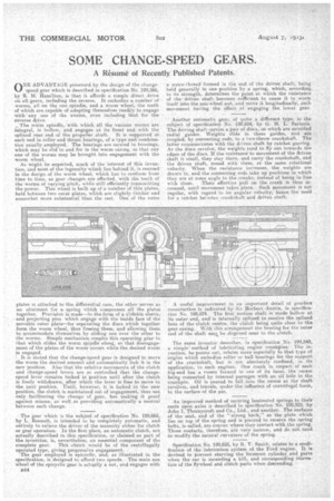
ONE ADVANTAGE possessed by the design of the changespeed gear which is described in specification No. 199,566, by R. M. Hamilton, is that it affords a simple direct drive on all.gears, including the reverse. It embodies a number of worms, all on the one spindle, and s worm Wheel, the teeth of which are capable of adapting themselves readily to engage with any one of the worms, even including that for the reverse drive.
The worm spindle, with which all the various worms are integral, is hollow, and engages at its front end with the splined rear end of the propeller shaft. It is supported at each end in roller and thrust bearings, of a type and combination usually employed. The bearings, are carried in housings, which may be slid to and fro in the worm easing, so that any one of the worms may be brought into engagement with the worm wheel.
As might be expected, much of the interest a this invention, and Most of the ingenuity which lies behind it, is centred in the design of the worm wheel, which has to conform from time to time, as gear changes are effected, with the teeth of the worms of varying pitch, while still efficiently transmitting the power. This Wheel is built up of a number of thin plates. held between two outer plates, which are slightly thicker and somewhat more substantial than the rest. One of the outer
plates is attached to the differential case, the other serves as an abutment for a spring which compresses all the plates together. Provision is made—ire the form of a slidable sleeve,. and projecting pins which engage with the inside face of the movable outer plate—fur separating the discs which together form the worm wheel, thus freeing them, and allowing them to acconimodate themselves by sliding one over the other to the worms. Simple mechanism couples this operating gear to that which slides the worm spindle along, so that disengagement of the plates of the worm'occurs while the desired worm is engaged.
It is stated that the change-speed gear is designed to move the worm the desired amount and automatically lock it in the new position. Also that the relative movements of the clutch and change-speed levers are so controlled that the changespeed lever remains locked in position until after the clutch is freely withdrawn, after which the lever is free to move to the next position. Until, however, it is locked in the new position, the clutch is maintained Out of engagement, thus not only facilitating the change of gear, but making it proof .against misuse, as well, as providing automatically a neutral between each change. • The gear which is the subject of specification No. 199,665, by L. Renault, is intended to be completely automatic, and entirely to relieve the driver of the necessity either for clutch or gear operation. In the first. place, an automatic clutch, not actually described in this specification, or claimed as part of the invention, is, nevertheless, an essential component of the complete gear. This clutch would be of the centrifugally operated type, giving progressive engagement. The gear employed is epicyclic, and, as illustrated in the specification, is designed to afford two speeds. The main sun wheel of the epicyclic gear is actually a nut, and engages with E44
a screw-thread formed in the end of 'the driVen shaft; being • held generally in one position by a spring, which, according..., to its strength, determines the point at which the resistance of the driven shaft becomes sufficient to cause it to worm itself into the sun-wheel nut, and Move it longitudinally, such movement having the effect if engaging the lower gear.
Another automatic gear, of quite a different type, is the subject of specification No. 199,654, by G.', M. L. Sartori. The driving shaft carries arjaair of discs, on which are mounted radial guides. 'Weights slide in these guides, and are • coupled, by connecting rods, to a two-throw crankshaft. The latter communicates with the driven shaft by ratchet gearing. As the discs revolve, the weights tend to fly out towards the edges of the discs. If the resistance to movement of the driven Shaft if stnall, they stay there, and carry the crankshaft, and the driven shaft, round with them, at the same rotational velocity. When the resistance increases, the weights are drawn in, and the connecting rods take up positions in which they are at some angle to the cranks, instead of being in line
with them. Their effective pull on the crank is thus increased, until movement takes place. Such movement is not. regular, with regard to its angular velocity; hence, the need for a ratchet between crankshaft and driven shaft.
A useful improvement in an important detail of gearbox eonsttuction is indicated by Sir Herbert Austin, in specification No. 199,574. The first. motion shaft is made hollow at its outer end, and -is internally splined to receive the splined boss of the clutch centre, the clutch being quite close to the gear casing. With this arrangement the bearing for the outer end of the shaft may be disposed near to the. clutch The same inventor describes, in specification No. 199,540, a simple' method of lubricating engine crankpins: The inyention, he points out, relates more especially to that type of engine which embodies rtiller or ball bearings for the support of the crankshaft, but. is not absolutely confined, in its application, to such engines.. One crank in respect of each big-end has a recess formed in one of its faces, the recess being connected by internal passages with an oil hole in the crankpin. Oil is caused to fall into the recess as the shaft revolves, and travels, Under the influence of centrifugal force, to the surface of the pin.
An improved method of securing laminated springs to their 'seats upon axles is described in specification No. 199,522, by John T. Thornycroft and Co., Ltd.' and another. The surfaces of the' seat, and of the ” strong back," as tho plate which lies on top of the spring and is pierced to receive the spring bolts, is called, are convex where they contact with the spring. Those contacts, therefore, are very narrow, and do not tend to modify the natural curvature of the spring.
Specification No. 199,625, by R. V. Smith, relates to a modification of the lubrication system of the Ford engine. It is devised to prevent starving the foremost cylinder and parts when the car is ascending a hill, and corresponding starvelion of the flywheel and clutch parts when descending.