


EQUIPPING A COACH FOR WIRELESS RECEPTION.
Page 24
If you've noticed an error in this article please click here to report it so we can fix it.
There are Many Ways of Coupling Valves for High-frequency Amplification. This Article Deals with the " Tuned-anode " Method.
'N the five articles on the subject of wireless equipment for the motor coach that have preceded this one, it has been pointed out that high-frequency amplification is very nearly a necessity on account of the very poor aerial that can be erected, even in
favourable circumstances. In the latest article of this series we outlined a method of high-frequency valvecoupling employing ironless transformers. This time we propose to describe an easier, and in many cases more efficient, manner of connecting a high-frequency valve to either a second one or to a detector.
The method is known as "the reactance-capacity method," to give it its full title. More commonly, it is referred to as "the tuned-anode " coupling,
although this latter appellation is entirely erroneous. It has the great advantages that it is easily rigged up from apparatus that is not necessarily specifically designed for this purpose alone, that it gives as great an efficiency of coupling as one likes (there is such a thing as having the coupling too good, and this will be explained later on), that it is reasonably easy to operate, and last, but by no means least, it enables us to make use of that desirable property of the ther miortic valve whereby, through the use of reactive or regenerative circuits, the signal strength maybe very
greatly augmented without the danger of causing seri ous interference to the whole wireless neighbourhood. It will be remembered that in a previous article the fundamental requirements of any system of coupling
valves was discussed, and it was pointed out that it was necessary to make provision for the maintenance of the steady plate voltage on the anode, or plate, of the valve without at the same time subjecting the grid' of the following valve to this same plate voltage, which would paralyse it. In the reactance-capacity method of valve coupling we make use of the desir able property of a condenser which will pass a high frequency current with little loss while offering an
impassable barrier to a direct current, however high the voltage (up to the breakdown point Of the insulation of the condenser).
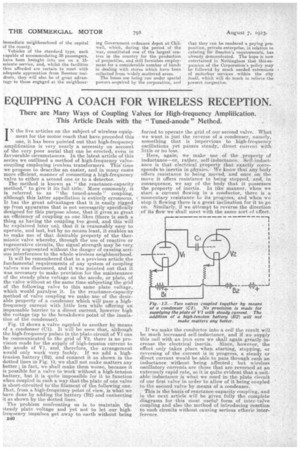
Fig, 13 shows a valve coupled to another by means of a condenser (01). It will be seen that, although the high-frequency pulses in the Plate circuit of VI can
be communicated to the grid of V2. there is no provision made for the supply of high-tension current to
the anode of V1, and, therefore, the arrangement would only work very feebly. If we add a hightension battery (82), and connect it as shown in the
dotted lines in Fig. 13, we shall not make matters any better ; in fact, we shall make them worse, because it is possible for a valve to work without a high-tension
battery, but it is quite impossible for it to function when coupled in such a way that the plate of one valve is short-circuited to the filament of the. following one. That, from a high-frequancy point of view, is what we have done by adding the battery. (B2) and connecting it as shown by the dotted lines.
The problem confronting us is to maintain the steady plate voltage and yet not to let our highfrequency impulses get away -to earth without being
E40
forced to operate the grid of our second valve. What we want is just the. reverse of a condenser, namely, something that is impervious to high-frequeitcy oscillations yet passes steady, direct current With little or no loss.
Here, again, we make use of the property of inductance—or, rather, self-inductance.. Self-induct.. anon is that electrical property that exactly corresponds to inertia in physics. We know that any body offers resistance to being moved, and once on the move it offers resistance to being stopped,. and, in consequence, we say of the body that it possesses the property of inertia. In like manner, when we start a current flowing in a conductor, there is a momentary resistance to its progress, and when we stop it flowing there is a great inclination for it to go on. Similarly, it we attempt to reverse the direction of its flow we shall meet with the same sort of effect..
If we make the conductor into a coil the result will be much increased self-inductance, and if we supply this coil with an iron core we shall again greatly increase the electrical inertia. Since, however, the effect only takes place when starting, stopping, or reversing of the current is in progress, a steady or direct eurrent would be able to pass through such an inductance without being affected ; but wireless oscillatory currents are those that are reversed at am. extremely rapid rate, so it is quite evident that a suitable inductance is what we need in the plate circuit of our first valve in order to allow of it being coupled to the second valve by means of a condenser.
This is the basis of reactance-capacity coupling, and in the next article will be given fully the complete diagrams for this most usefat form of inter.valve coupling and also the method of introducing reaction to such circuits without causing serious etheric interference.