


AN ENTIRELY NEW 30-40-CWT. SUBSIDY LORRY.
Page 14
Page 15
If you've noticed an error in this article please click here to report it so we can fix it.
Details of a Remarkable Chassis Built by Clement-Talbot, Ltd., to Meet the Demand of the War Office for a Lorry Entitling Users to a Subsidy.
I N OUR issue elated August 1st, 1922, -we gave a resttme of the specification for a'30-cwt. vehicle-issued by the War Office to various manufacturer.s who could, to a great extent, employ their initiative , in design, so long asthe chassis conformed with certain requirements, so that therewas little question of stifling individual enterprise and freedom of design.
Several makers are constructing suitable chassis; amongst these are ClementTalbot, Ltd., who have just completed a most striking vehicle, embodying some very interesting features in design, and yet -fulfilling the conditions of the subsidy scheme; particulars of which are about to be issued by the Army Council.
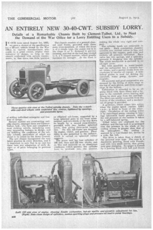
The new chassis' incorporates the very latest practice in every direction, and it is important to note that in no case has there been any adaptation of early designs or of parts belonging to previous types. The chassis consists of a pressed channel steel frame, provided 'with three main cross-members, of which the front is of a simple type, the centre one is in the shape of an X, designed to prevent twisting, and that -at the end has, riveted to it, a V-shaped member, which greatly increases its strength. At the front is
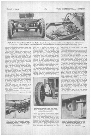
an elliptical sub-frame, supported by a large spherical joint • in the front crossmember, and two-thirds of the way down its length by a second cross-member, provided with two further spherical joints, thus giving three-point suspension. On this sub-frame are mounted the engine, clutch, and gearbox. Flexibility 'is also .pertnitted to the radiator, which is carried on spherical rubber supports. . The power unit has four cylinders of 100 nun, bore and 130 mm stroke, cast en bloc and mounted on an abasninium crankcase; which permits The 'cylinder bore ti protrude into the interior, snaking the whole very rigid and compact.. The cylinder heads are removable in one piece. Each combustion chamber contains two vertical valves in line, and operated, by flat tappets push rods, and rockers, all pressure lubricated. Each • valve has two springs, and a' split-ring prevents ft dropping into the cylinder. The whole mechanism is enclosed in an oil-tight cover. The inlet Manifold is Water-heated, and the carburetter has a variable hotair intake, and a partial intake from the crankcase to recover oil vapour. A wide helical pinion is • used for driving the camshaft-, water pump, dynamo, and _magneto.
Oil economy and good compression are ensured by the fitting of three rings at the top of each piston, and three scraper rings at the bottom. Lubrication is attended to by an oil pump fitted with three filters and a bypass to the camshaft centre bearing and driven by skew gear from the camshaft. The filters are readily accessible from the bottom of the crankcase, and a mechanical oil 'gauge is provided. A governor, which comes into action when the engine speed reaches 2,000 r.p.m., is fitted in front of the crankshaft. Circulation of, the cooling water is by centrifugal -pump, running in hearings lubricated under pressure, whilst the end pressure of the turbine is taken by a self-balanced spring.
Gilled tubes are employed for the radiator, and the top tank is so arranged thatthepressure in the whole of the cooling system is greater than that ef the atmosphere. The cooling is assisted by a four-bladed fan, driven by a wide, flat belt.
The drive is taken from a clutch of the inverted cone type. The cone is a daralumin pressing, faced with Ferodo, and with very small inertia, thus giving easy gear changing, Its spigot is formed by a housing fitted with ball and thrust bearings, absolutely protected from the ingress of water or dust and with an oil hole for lubrication.
Between the clutch and gearbox is a flexible joint, consisting of two discs, each composed of three spring steel plates. The clutch-operating gear is situated inside the front portion of the gearbox, and is, therefore, automatically lubricated. It is provided with a worm adjustment and a large clutch stop. The splines on which the clutch member slides are also in the gearbox.. Continuing with the gearbox, the layshaft is situated directly under the main shaft, it is mounted on double-row ball bearings, and the gears are of ample dimensions. The operating mechanism forms a unit bolted to the top of the gearbox casing; it consists of a frame containing two sliding forks, a reverse lever, and an interlocking mechanism with spring plungers. The change-speed lever is mounted directly above this, and articulates on a spherical joint,the reverse stop being operated by pressing down the ball, on the top of which the different speeds are clearly indicated.
On the cover of the gearbox is a powerful tyre pump, with easily accessible valves, and a sliding gear which engages when required with the constantmesh pinion.
Great precaution has been taken everywhere to ensure the exclusion of. dirt and water and tu preyent the leakage of oil. This is exemplified by. the torque tube spherical joint; which is provi±ded with a rubber sleeve. To the gearbox are. fitted all the main controls, including the pedal gear for the foot brake, the hand-brake lever, and accelerator pedal.
Owing to the fact that the-vehiele has particularly large wheels, it has been essential to build a back axle of great strength, as the tangentical lead on the gears is very considerable; for the same reason it has been necessaryto retain a low gear ratio; double-reduction gearing bas, therefore, been resorted to.
The bock axle proper is formed of two malleable castings assembled vertically and securing between them the torque tube, which forms a sub-unit. On each side of the braising thus formed are steel tubes, of varying. thickness.
The final drive gear •consists of double helical spur wheels and straight tooth bevels. The bevel pinion it mounted on three roller bearings and has two thrust races. The bevel crown whe61 is carried on the intermediate shaft, and. alongside it ia,a double helical pinion engaging the large wheel secured to the differential box. This iritermecliate shaft is carried on two Timken roller bearings. Bevel gearing is also employed for the differential, in which there are four satellite pinions.
The rear springs bear an extensions of the brake anchorages, the lubrication at the bearing points being automatically
provided from the axle -casing. • • . It will be seen by referring to the illustration that the wheels... are of a very unusual type. Each consists of a large steel casting in the shape of an undulated disc, lightened by openings and formed in one piece with the hub. The rear wheels are carried on large Timken roller bearings, and the drive to them is external, flanges being formed en the axle ,shafts. and these passing through end being directly bolted to the outsides of the wheel hubs. To the inside of each rear wheel is bolted a brake drum, which is a steel ring of large diameter ribbed to facilitate cooling. In these drums are die-cast aluminium shoes, faced with Ferodo.
The front axle consists of a large stamping, each side terminating in a fork bored to receive the two Timken .bearings which support the swivel pin. Each front hub is formed by a stationary steel casting, into which is forced the swivel pin, it contains two large Timken bearings, inside which runs the wheel spindle.
The steering gear is of the worm and nut type, end the casing forms an Oil intik.