


Patents Completed.
Page 20
If you've noticed an error in this article please click here to report it so we can fix it.
Complete specifications of the following patents will be sent to any address in the United Kingdom by the Sale Branch, Patent Office, Holborn, WC., upon receipt of eightpence per copy.
Detachable Rims for Transport Vehicles.
The Daimler Motoren-Gesellsehaft, No. 14,757/12, dated under International Convelition, 24th June, 1911.—According to this invention the rims carrying the tires are detachable from the road wheels in a very simple manner. The rubber tires
are mounted on steel rings which aro forced by hydraulic pressure on to rims of smaller diameter, the internal diameter of these rims is greater than that of the felloe of the wheel, thus preventing the rims from jamming if rusted up. The tires are preferably mounted on two rings which are placed side by side on the felloe of the wheel, the rings carrying the tires are held in contact with the wheel by means of wedges. These wedges are arianged so that they taper alternately, one being driven in from the outside of the wheel and the next one is driven from the inside, and so on. It will thus be seen that to loosen the detachable rims it is only necessary to knock the wedges out with a drift, which is smaller in width and thickness, but longer than the wedges, this drift being inserted into the small and unoccupied ends of the grooves.
Ignition Timing Device.
Hartmann and Braun AkL.—Ges., No. 19,fl3/12, dated under International Convention, 31st August, 1911..---This inven
tion relates to means for automatically controlling the timing in magneto ignition apparatus and has for its object, to advance the sparking to the precise extent desired. The timing adjustment which is of the centrifugal governor type is provided with means whereby the maximum ignition advance; which is determined by experiment, can be subsequently adjusted without dismantling any of the apparatus. In its simplest form the construction employed according to this invention consists in arranging adjustable stops in the governor casing; the stops may be screws operated from outside the casing and will limit the outward throw of the fly-weights. These weights are, of course, thrown outwards owing to centrifugal force, and are suitably connected to effect the automatic timing of the sparking according to the speed of the engine. Means are also provided for varying the adjustment of the maximum advance while the engine is in motion.
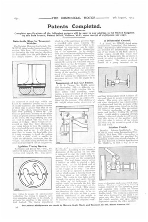
Suspension of Rail Car Bodies. J. C. P. Thomas, No. 20,942, dated 13th September, 1912.—A difficulty encountered with bogie vehicles lies in their action when travelling round curves, a large proportion of the weight being transferred to one side and is supported by friction plates on rollers provided for the purpose. This shifting of the weight causes undue depression. of
springs and so increases the cant of the vehicle. According to this invention depression of the springs on one side is arranged to sway the whole body towards the opposite side thus tending to decrease the weight on the compressed springs. The bogie frame shown carries a bracket on which is pivoted a bellcrank lever. At the left-hand end of this lever is a roller which takes part of the weight of the body. The other end of the lever supports a transverse spring which carries a bearing block for the king pivot at the middle of the bogie. The weight is thus taken partly through this spring and partly through the roller by the hell-crank. If the vehicle cants, say towards the left, the roller on that side is depressed and the bell-crank lever is tilted. This causes the transverse spring and the king pivot, and therefore the whole body, to be carried towards the right so that a more uniform distribution of the weight is obtained. The action of the device may be adjusted to suit any required condition.
A Differential Control.
J. A. Hardy, No. 3532113, dated under International Convention, 12th February, 1912.—According to this invention means are provided for automatically braking one of the wheels on the back axle of a motor vehicle, should this wheel race owing to its leaping into the air due to a shock, or owing to skidding on a wet or greasy surface. The means employed consist of a pump mounted on an auxiliary divided shaft which is driven off the road wheels by means of suitable gear wheels. This pump acts against itself, and when the speed of one wheel reaches a predetermined limit the pressure of the fluid in the pump casing is such as to stop the action of the pump, thus preventing the relative movements of the pump parts, and in effect, locking the divided shaft. As this shaft is connected through gearing to the road wheels, it will be seen that this locking of the auxiliary shaft will also effect. a locking of the wheels and thus stop the excessive speed of the one road wheel.
Friction Clutch.
Daimler Motoren-Gesellschaft, No. 14,756/12, dated under International Convention, 24th June, 1911.—According to this invention means are provided for operating double cone friction clutches of the type described in British Specification No. 19,585/11, in such a way as to en gage or disengage each cone clutch separately. This is accomplished by means of wedges mounted on the operating pedal and engaging with rollers on sleeves attached respectively to each cone of the double clutch. The wedge is so mounted, that when depressed by the pedal it engages one roller first, thus disengaging one clutch member, and upon further depression operates the other member.