


Swash-plate Transmission Mechanism
Page 36
If you've noticed an error in this article please click here to report it so we can fix it.
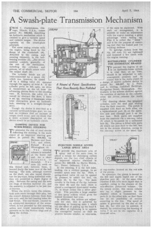
FROM C. Frederickson, Chicage, Illinois. -U.S.A., comes patent No. 558,992, describing an hydraulic mechanism which is claimed to give a variable speed and variable torque. The device operates on the swath-plate principle.
The outer casing rotates with the engine, being fixed to the flange of the crankshaft (6). ' Attached to the casing, and. rotating therewith, is the ballbearing wolibler (5). .The driven member consists, generally, of the rest of the mechanism, ' including the cylinders and pistons, all of which rotate with the output shaft (4).
The cylinder heads are all inter-connected by a space (2) which can, however, be closed off by a sliding valve . (1) operated through the agency of-lever 3. If the cylinder ports be left open, no drive is transmitted, as the oil from the advancing pistons flows to the receding ones. •If, however, the valve (1) be moved to obstruct the flow, -a drive is set up, reaching a maximam when total obstruction gives an hydraulic, lock, resulting in a straight-through drive.
Though the device is described as a variable speed-and-torque gear, we can find no evidence that an increase of torque could occur, and we think that a more accurate description of the device would be an hydraulic clutch, DAMPING DEVICE FOR WORM-WHEEL STEERING
TO minimize the risk of road shocks deflecting the steering, is the main object of an improved steering gear shown in patent No. 559,063, by Burman and Sons, Ltd., and others, Ryland R a a d, Birmingham, 15.
T h e steering column is extended at its lower end and, for .a short distance, is threaded: T w o nuts (2) work on this thread and, between them, is located freely the inner race of the ball bearing. The nuts, although screwed on the shaft, are also keyed thereto, but the keyways, being somewhat wide, they are permitted a slight degree of play. Between the casing and the nuts are rings of friction material (1), and the assembly is adjusted to be just free of friction.
When the driver turns the column, both nuts move through their play, but the overall distance between them does not vary, and the ball bearing takes the end thrust. The end thrust, created by an attempted movement of the wormwheel, is not preceded by this screwing action and would immediately bring pressure on to the friction rings and so damp the motion. 339,063 !Fiji
.1104„
'04441
\N erprovide the maximum area of spray and at the same time, to afford a means for dislodging carbon deposit, • are the two chief objects of an improved injector disclosed in patent No. 558,928, by Martin Motors, Inc., Dover, Delaware, U.S.A.
In the drawing, 3 is the fuel inlet, leading, via a vertical passage, to an annular space near the tip. Here, a spring-closed valve (4) can be opened by pressure, to admit the fuel, via splines (5), to the tip. . The main novelty is the form of the tip; between the head (6) and the body there is placed a corrugated sheet-metal washer (7), in shape rather like a mitre gearwheel. This provides a large number of fine spray orifices which gives the desired increased fuel "area.
In addition, the orifices are adjustable for size; this is achieved by tightening or loosenIng nuts 1 which has the effect of pulling up the head 6. The effect of tightening is to squeeze the corrugated washer so that its grooves become smaller, or vice-versa, if the nuts be slackened. With such an arrangement, it is possible to make an adjustment with the engine running, a great advantage when tuning up. Pipe 2 is called the " bleed " and is for the purpose of removing fuel that has leaked past the working surfaces.
To slodge cbrbon from the
4. tip, the nuts (1 ) are tightened and loosened a few times with the engine running.
SUCTION-FREE CYLINDER FOR HYDRAULIC BRAKES
TOprevent the ingress of air in an hydraulic-brake system it is vital that, at no time, should it be subjected to subatmospheric pressure and to ensure this is the main object of a design of master cylinder shown in patent No. 558,857, by J. Pratt and A. Girling, Guildhall Buildings, Navigation Street, Birmingham, Particularly is the scheme directed against the creation of suction in the cylinder when the driver releases the brake pedal. The drawing .shows the proposed• cylinder, with the feed pipe leading from the fluid reservoir. The piston is supplied with fluid on both sides, via A. replenishment port (5) on the operative side and through port I on the rear face. Both ports are supplied from the reservoir via a one-way valve (7) which is by-passed by a calibrated leak (6). The piston is fitted with ports (3) which can pass fluid to the left, but not in the reverse direction, owing to the one-way action of the usual type
of cup-Washer located on the rod side of the piston,
In operation, the piston is moved to the left and expels liquid out of the pipe-line port (4). At the same time chamber 2 fills with more liquid than is .expelled, owing to the absence of the non-effective. piston-rod volume. On the return stroke, this excess vedume sets up a slight . pressure in the chamber which is transmitted, via ports 3, to the other side, so that there can be no possibility of suction occurring in the line. The speed of return is governed by the size of the leak (6), but this can be assisted, if desired, by constructing the housing of valve 7 to. act in the capacity of a tilow.off valve.