


Latest Girling "Two-leading-shoe" Brake
Page 29
If you've noticed an error in this article please click here to report it so we can fix it.
Design Improved in Respect of Symmetry and New Means for Shoe Positioning Incorporated
TO avoid off-set loading and to utilize roiled sections which have already been standardized, New Hudson, Ltd.; Icknield Street, Birmingham, has modified the design of its Girling two-leading-shoe brake, which was described and illustrated in our issued dated November 25, 1938. The principle of operation, however, remains unchanged. The familiar Girling expander unit is used as before, also the standard Girling adjuster. That which would normally be the leading shoe is also of conventional type, although for special application in vehicles that are subject to much reverse running, both shoes would be of the special design in which, in addition to the shoe proper, there is a separate part called the shoe carrier.
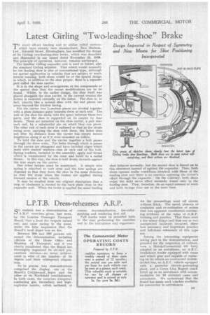
It is in the shape and arrangement of the components of the special shoe that the recent modifications are to be found. Whilst, in the earlier design, the shoe itself was placed alongside the shoe carrier, in the current version the former is mounted centrally on the latter. The shoe is, in fact, exactly like a normal shoe with the end pieces cut away beyond the friction facing.
For the carrier two L-section pieces are riveted together with a plate distance piece between them at each end. The• web of the shoe fits easily into the space .between these two parts. and the shoe is supported on its carrier by four struts. These, are mounted on the shoe carrier, a pair near each end, by a substantial pin on which they can pivot. The other end of each strut is radiused so that as the struts swing over, carrying the shoe with them, the latter does not alter its distance from the carrier but simply moves lengthwise along it as if it were mounted on rollers.
To hold the shoe and the carrier together a bolt passes through the three webs. The holes through which it passes in the carrier ate elongated and have bevelled edges which mate with conical washers—one at each end of the bolt. Spring washers, included in the assembly, apply end thrust which is transformed by the cone and bevel to a radial thrust. In this way, the shoe is held firmly inwards against the four struts on the carrier,
One other feature must be mentioned. A simple wire spring is attached to each strut and the four springs are disposed so that they force the shoe in the same direction as does the drum when the brakes are applied during forward motion of the vehicle.
It may be recalled from our original description that a stop or abutment is riveted to the back plate close to the expander unit. When the brake is applied the usual leading
shoe behaves normally, but the second shoe is forced on to this abutment instead of against the expander. Thus, both shoes operate under conditions identical with those of the leading shoe and there is no reaction opposing the driver's effort through the expander. On the contrary, both shoes enjoy the mild servo effect normally found only in the . leading shoe. They, therefore, do an equal amount of work and both facings wear out at the same time.