


Relieving Springs of Side Thrust
Page 76
If you've noticed an error in this article please click here to report it so we can fix it.
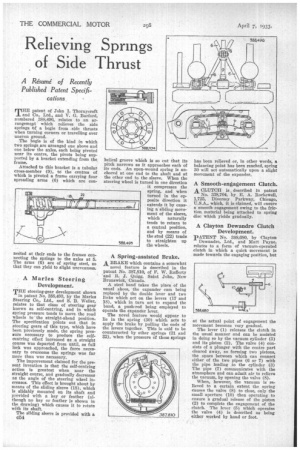
A Resume' of Recently Published Patent Specifi-, cations T"patent of John I. Thornycroft and Co.. Ltd., and V. G. Barford, numbered 388,496, relates to an arrangemept which relieves the side springs iof a bogie from side thrusts when turning corners or travelling over uneven ground.
The bogie is of the kind in which two springs are arranged one above and one below the axles, each being pivoted near its centre, the pivots being sunported by a bracket extending from the frame.
Attached to this bracket is ft tubular cross-member (9), to the centres of which is pivoted a frame carrying four spreading arms (6) which are con nected at their ends to the frames connecting the springs to the axles at 5. The arms (6) are of spring steel, so that they can yield to slight unevenness.
A Manes Steering Development.
THE steering-gear development shown
in patent No. 388,493, by the Marles Steering Co., Ltd., and S. B. Weller, relates to that class of steering gear known as self-centring, and in which spring pressure tends to move the road wheels tothe straight-ahead position. The specification points out that in steering gears of this type, which have been previously made, the spring pressure necessary to produce the selfcentring effect increased as a straight course was departed from until, as full lock was approached, the force necessary to overcome the springs was far more than was necessary.
The improvement claimed for the present invention is that the self-centring action is greatest when near the straight course, and gradually decreases as the angle of the steering wheel increases. This effect is brought about by means of the sliding sleeve (18), which is slidably mounted on its shaft and provided with a key or feather (although no key or feather is shown in the drawing) which causes it to rotate with its shaft.
The sliding sleeve is provided with a C54 helical groove which is so cut that its pitch narrows as it approaches each of its ends. An open-wound spring is anchored at one end to the shaft and at the other end to the sleeve. When the steering wheel is turned in one direction it compresses the spring, and when turned in the opposite direction it extends it by causing a sliding movement of the sleeve, which naturally tends to return to a central position. and by means of the stud (22) tends to straighten up the wheels.
A Spring-assisted Brake. A BRAKT1 which contains a somewhat
novel feature is described in the patent No. 387,810, of F. W. Rafferty and R. J. Quigg, Saint John, New Brunswick, Canada.
A steel band takes the place of the usual shoes, the expander cam being replaced by the double lever and two links which act on the levers (17 and 18), which in turn act to expand the band, a push-rod being employed to operate the expander lever.
The novel feature would appear to lie in the spring (30) which acts to apply the brake by pulling the ends of the levers together. This is said to be counteracted by other springs (31 and 32), when the pressure of these springs
has been relieved or, in other words, a balancing point has been reached, spring 30 will act automatically upon a slight movement of the expander.
A Smooth-engagement Clutch.
A CLUTCH i.e. described in patent
No. 338,704, by E. A. Rockewell, 1,725, Diversey Parkway, Chicago, U.S.A., which, it is daimed, will ensure a smooth engagement owing to the friction material being attached to spring disc which yields gradually.
A Clayton Dewandre Clutch Development.
PATENT No. 388,680, by Clayton Dewandre, Ltd., and Matt Payne, relates to a form of vacuum-operated clutch in which a quick movement is made towards the engaging position, but at the actual point of engagement the movement becomes very gradual.
The lever (1) releases the clutch in the usual manner and can be assisted in doing so by the vacuum cylinder (3) and its piston (2). The valve (4) consists of a plunger with the centre part cleared away, so forming two pistons, the spate between which can connect either of the two pipes (6 or 7) with the pipe leading to the cylinder (3) The pipe (7) communicates with the atmosphere and can admit air to relieve the vacuum, by opening the valve (8). When, however, the vacuum is re= lie-red to a certain extent the spring causes the valve (8) to close, only the small aperture (10) then operating to ensure a gradual release of the piston (2) to complete the engagement of the clutch. The lever (5) which operates the valve (4) is described as being either worked by hand or foot.