


H ot summers tend to dispel all thoughts of winter, cold
Page 105
Page 106
Page 107
If you've noticed an error in this article please click here to report it so we can fix it.
weather and shivering nights in a truck cab. Traffic jams and blazing hot sun concentrate minds on the desirability of air conditioning instead. But as the 900 summer of '90 becomes a memory, this is the time to consider auxiliary cab heating, well before it's needed.
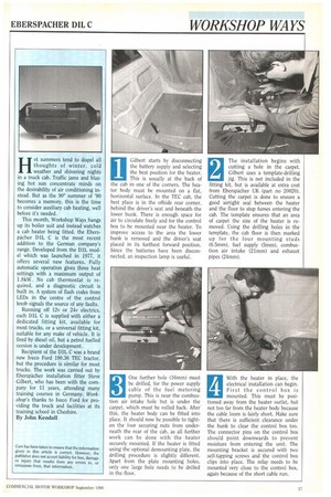
This month, Workshop Ways hangs up its boiler suit and instead watches a cab heater being fitted. the Eberspacher D1L C is the most recent addition to the German company's range. Developed from the D1L model which was launched in 1977, it offers several new features. Fully automatic operation gives three heat settings with a maximum output of 1.8kW. No cab thermostat is required, and a diagnostic circuit is built in. A system of flash codes from LEDs in the centre of the control knob signals the source of any faults.
Running off 12v or 24v electrics, each DlL C is supplied with either a dedicated fitting kit, available for most trucks, or a universal fitting kit, suitable for any make of vehicle. It is fired by diesel oil, but a petrol fuelled version is under development.
Recipient of the DlL C was a brand new Iveco Ford 190.36 TEC tractor, but the procedure is similar for most trucks. The work was carried out by Eberspacher installation fitter Steve Gilbert, who has been with the company for 11 years, attending many training courses in Germany. Workshop's thanks to Iveco Ford for providing the truck and facilities at its training school in Cheshire.
By John Kendall
Gilbert starts by disconnecting the battery supply and selecting the best position for the heater. This is usually at the back of the cab in one of the corners. The heater body must be mounted on a flat, horizontal surface. In the TEC cab, the best place is in the offside rear corner, behind the driver's seat and beneath the lower bunk. There is enough space for air to circulate freely and for the control box to be mounted near the heater. To improve access to the area the lower bunk is removed and the driver's seat placed in its furthest forward position. Since the batteries have been disconnected, an inspection lamp is useful.
1
The installation begins with cutting a hole in the carpet. Gilbert uses a template-drilling jig. This is not included in the fitting kit, but is available at extra cost from Eberspacher UK (part no 20020). Cutting the carpet is done to ensure a good airtight seal between the heater and the floor to stop fumes entering the cab. The template ensures that an area of carpet the size of the heater is removed. Using the drilling holes in the template, the cab floor is then marked up for the four mounting studs (6.5mm), fuel supply (5mm), combustion air intake (21mm) and exhaust pipes (24mm).
3 One further hole (16mm) must
be drilled, for the power supply cable of the fuel metering
pump. This is near the combustion air intake hole but is under the carpet, which must be rolled back. After. this, the heater body can be fitted into place. It should now be possible to tighten the four securing nuts from underneath the rear of the cab, as all further work can be done with the heater securely mounted. If the heater is fitted using the optional demounting plate, the drilling procedure is slightly different. Apart from the plate mounting holes, only one large hole needs to be drilled in the floor.
With the heater in place, the electrical installation can begin. First the control box is mounted. This must be positioned away from the heater outlet, but not too far from the heater body because the cable loom is fairly short. Make sure that there is sufficient clearance under the bunk to clear the control box too. The connector pins on the control box should point downwards to prevent moisture from entering the unit. The mounting bracket is secured with two self-tapping screws and the control box clips into place. The relay needs to be mounted very close to the control box, again because of the short cable run. The control box and relay are now connected up to the wiring loom. Ideally the control rheostat should be positioned where it can be reached from either driving seat or bunk. The centre console is the obvious position and a convenient blanking plug provides a good location for this. The carpet must again be lifted to run the cable from the control box to the console. Then the six-core cable must be cut to length. The wires are stripped, a spade connector crimped on and fitted into a connector block ready to plug into the switch. The manufacturer's instructions indicate which cable connects to which switch terminal.
5
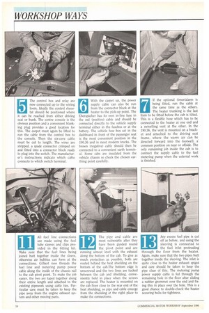
With the carpet up, the power supply cable can also be run from the connector block at the heater to the pick-up point. The Eberspacher has its own in-line fuse in the red (positive) cable and should be connected directly to the vehicle supply terminal either in the fusebox or at the battery. The vehicle fuse box set in the dashboard in front of the passenger seat is the most convenient position in the 190.36 and in most modern trucks. The brown (negative) cable should then be connected to a convenient earth terminal. Some cabs are insulated from the vehicle chassis so check the chosen earthing point carefully. If the optional timer/alarm is being fitted, run the cable at the same time as the others. The heater trunking is the last item to be fitted before the cab is tilted. This is a flexible hose which has to be connected to the heater at one end and a swivelling vent at the other. In the 190.36, the vent is mounted on a bracket and attached to the driving seat frame, where the warm air can be directed forward into the footwell, a' common position on near or offside. The only remaining job inside the cab is to connect the supply cable to the fuel metering pump when the external work is finished. After the cab is tilted Gilbert mounts the fuel metering pump on the inside of the chassis rail near the fuel tank. This should be about a metre from the feed point on the fuel tank and inclined at about 15° to the horizontal. Fuel flow through the pump is indicated with an arrow and the output line to the heater (the white tubing) is the upper connection. The supply line from the tank (the black tubing), is passed up the inside of the chassis rail and cut to length. A sharp blade or cutting tool must he used — do not use side cutters as this will constrict the narrow bore and could cause a blockage in the fuel line. The standpipe, which picks up diesel from the vehicle's fuel tank to feed the healer, is supplied in a standard length and must be cut according to the depth of the fuel tank, which is done by holding • the pipe against the side of the tank and measuring it to a point approximately 25mm from the bottom. This ensures that the heater will operate even when the vehicle fuel level is quite low, but without picking up sediment from the bottom of the tank. As a further precaution against sediment blockage, the pipe should be cut off at an angle of 45°. The fuel metering pump incorporates a fuel filter to block small particles.
10 Each kit is supplied with a
sachet of gel for sealing ex ternal electrical connec tions. This can also be used for coating the bit when drilling the fuel tank for the supply standpipe to prevent swarf from dropping into the tank. Before drilling make sure that the fuel gauge float will not be obstructed and that the hole is not directly over one of the tank baffles which prevent fuel from surging back and forth. On the 190.36, the front section of the tank is clear of internal obstructions. The hole must be large enough for the standpipe's internal holding tabs to fit against the inside of the tank.
11
All fuel line connections are made using the fuel tube sleeves and clips provided in the fitting kit. Make sure that the fuel lines being joined butt together inside the sleeve, otherwise air bubbles can form at the connections. Gilbert now threads the fuel line and metering pump power cable along the inside of the chassis rail to the cab pivot point. To make the job easier, the two are taped together along their entire length and attached to the existing pipework using cable ties. Particular care must be taken to keep the pipe away from the engine exhaust system and other moving parts.
12
The pipe and cable are most vulnerable after they have been guided round the pivot point and are running almost level with the exhaust along the bottom of the cab. To give as much protection as possible, both are routed behind the heat shielding on the bottom of the cab.The bottom edge is unscrewed and the two lines are tucked between the cab and shielding, conveniently held in place when the screws are replaced. The heater is mounted on the cab floor close to the rear end of the heat shielding, so pipe and cable emerge from the shielding at the right place to make the connections.
13
Any excess fuel pipe is cut off as before, and using the sleeving is connected to the fuel inlet protruding through the floor from the heater. Again, make sure that the two pipes butt together inside the sleeving. The inlet is quite close to the heater exhaust spigot and care should be taken to keep the pipe clear of this. The metering pump power supply cable is fed through the remaining hole in the floor after sliding a rubber grommet over the end and fixing this in place over the hole. This is a good chance to double-check the heater securing bolts for tightness.
14 The final external job is to
fit the pipes to the com bustion air inlet and ex haust spigots. The air inlet pipe (black) should be positioned away from the exhaust. Both pipes should be run with a minimum length of 0.2m and a maximum of 2.0m. Gilbert cuts the inlet pipe and clips it to the underside of the cab. The exhaust pipe becomes hot in operation so it should be positioned protruding to the rear or side of the cab allowing water to drain from it and preventing fumes from accumulating under the cab. Dirt, water and snow should not be able to enter the pipe causing combustion problems.
15 After the exhaust is cut and
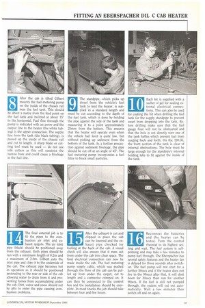
clipped in place the cab can be lowered and the ex haust pipe checked for fouling at the back of the cab. A visual check will also ensure that it runs out from under the cab into clear space. The final electrical connection can now be made inside the cab. The fuel metering pump supply cable, which was pushed through the floor of the cab can be pulled up from under the carpet, cut to length and a connector crimped on. It can then be connected to the control box and the installation should be complete. In most trucks the job should take between four and five hours.
16 Reconnect the batteries
and the heater can be tested. Turn the control
rheostat to its highest setting and wait. The fuel system is selfprim ing and may take a few minutes to pump fuel through. The Eberspacher has several safety features and the heater fan is delayed for three seconds after switchon. The fuel pump will not start for a further 50secs and if the heater does not fire in the 90secs after that, it will shut down for 30secs then run for another 90secs. lithe fuel is still not pumped through, the system will cut out automatically. Wait a few minutes then switch off and on again.