 1
1 2
2 3
3 4
4 5
5 6
6 7
7 8
8 9
9 10
10 11
11 12
12 13
13 14
14 15
15 16
16 17
17 18
18 19
19 20
20 21
21 22
22 23
23 24
24 25
25 26
26 27
27 28
28 29
29 30
30 31
31 32
32 33
33 34
34 35
35 36
36 37
37 38
38 39
39 40
40 41
41 42
42 43
43 44
44 45
45 46
46 47
47 48
48 49
49 50
50 51
51 52
52 53
53 54
54 55
55 56
56 57
57 58
58 59
59 60
60 61
61 62
62 63
63 64
64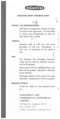 65
65 66
66 67
67 68
68 69
69 70
70 71
71 72
72 73
73 74
74 75
75 76
76 77
77 78
78 79
79 80
80 81
81 82
82 83
83 84
84 85
85 86
86 87
87 88
88 89
89 90
90 91
91 92
92 93
93 94
94 95
95 96
96 97
97 98
98 99
99 100
100 101
101 102
102 103
103 104
104 105
105 106
106 107
107 108
108 109
109 110
110 111
111 112
112 113
113 114
114 115
115 116
116 117
117 118
118 119
119 120
120 121
121 122
122 123
123 124
124 125
125 126
126 127
127 128
128 129
129 130
130 131
131 132
132 133
133 134
134 135
135 136
136 137
137 138
138 Fully enclosed alternator with transistorized control
Page 21
Page 25
If you've noticed an error in this article please click here to report it so we can fix it.
by Paul Brockington
CAV INTRODUCES THE AC 203 GIVING HIGH OUTPUT AT ENGINE TICK-OVER SPEEDS AND A SERVICE LIFE OF 250,000 MILES
• A heavy-duty alternator announced by CAV Ltd, has a cut-in speed of 700 rpm and a maximum-load speed of 1,350 rpm while the temperature range is +70deg C to —40deg C. The alternator is known as the AC 203 and as these data indicate, its design enables maximum output to be obtained at engine tick-over speeds and provides reliable operation in arctic or tropical conditions.
A fully transistorized current/voltage regulator, specially designed for the AC 203 permits the machine to deliver a maximum output (hot) of 60amp at a nominal 24V. It is claimed that controlling environment is unnecessary in the interests of performance apart from limitation of maximum ambient temperature to 70deg C.
An 85amp version of the AC 203 alternator has also been announced. This is a 24-V machine that is identical mechanically with the AC 203 60amp alternator. It has a cutting in speed (hot) of 950 rpm and a maximum output of 85amp (hot) at 1,500 rpm.
CAV claims an outstanding maintenancefree service life for the AC 203. It is said that the machine can be hosed-down or steamcleaned as required to remove dirt or oilcaked mud. Servicing comprises injecting a small amount of grease into the two nipples of the alternator at intervals of 50,000 miles. The machine is rated to operate 250,000 miles between major overhauls, if this distance is covered in less than 10,000 hrs or five years. Otherwise, the machine should be overhauled on one or other of the time bases, whichever comes first, Evolution of the AC 203 was preceded by a detailed examination of operational requirements and evaluation of existing machines. It was particularly noted that reliability over extended periods required a machine capable of coping with continuous exposure to water, mud and salt spray. And that a long service life depended on complete exclusion of foreign matter and prevention of corrosion internally. To cater for these requirements it was decided to design the machine as a totally enclosed unit, and this created the problem of providing sufficient heat dissipation. The problem could have been overcome by stipulating installation in an exposed position and restricting the temperature of operation to a maximum ambient temperature of 25deg C. But this was rejected as being incompatible with an acceptable concept of performance.
CAV technicians therefore opted for surface cooling and every component of the machine was designed to accommodate cooling by this means. In addition to developing high-grade bearings and oil seals for the unit, this necessitated providing good thermal contact of the stator with the yoke, reducing the number of coils per phase to lower stator heating and employing rectifier-bridge heat sinks in contact with the slip-ring end shield. A fan was fitted on the rotor shaft at the slip-ring end, an end shield was used having fins that gave a large cooling area and the machine was equipped with a shroud that protected the fan blades and directed the air flow over the end shield.
Preventing excessive heat build-up inside the machine posed a major problem. Heat generation had to be reduced and this could only be achieved by reducing the resistance of the conductors. Employing conductors having a large cross-section area was rejected as a solution on the score that it would create production difficulties. Using eight poles in place of 12 would have increased the effect of armature reaction per pole by 50 per cent, which would have made it difficult to obtain maximum output.
Reducing the effective number of turns in the stator coils increases the output of the machine and therefore the heat generated. If, however, the current is accurately regulated, the rated output can be obtained with the generation of less heat. This offered a means of overcoming the problem if a suitable regulator could be produced. None existed, so CAV developed a current /voltage regulator specifically for the unit based on well-tried electronic techniques.
Control is achieved by using the voltage drop across a precisely engineered shunt carrying the output current to influence a differential amplifier and thus obtain a switching signal. This operates the driver stage of the regulator to control the alternator output by field switching. Voltage control is obtained by measuring the system voltage with a Zener diode as a reference level and by again using alternator field switching to regulate output.
As battery charging progresses, control of output changes from current control to voltage control. Performance is virtually unaffected by temperature.
Powered wheel for battery electrics
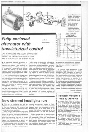
• A motor-in-wheel unit has been developed by Cav Ltd. for battery-electric trucks of all kinds. The reduction gearing as well as the electric motor is incorporated in the hub of the wheel. It is made in three types, all of which may be employed as a steered or fixed wheel and used in any combination, including single or double drive.
The unit's gyratory gearing was developed by P. R. Motors which also manufactures the gear, and it provides a single-stage reduction that minimizes power losses. Braking is by means of a cable-operated double-shoe mechanism acting directly on the motor armature. Designed for stirrup mounting, the rotating wheel hub is carried on ball-bearings adjacent to the stirrup fork.
In the case of the Type 13 the wheel has a diameter of 13in., the gearing gives a reduction ratio of 13 to 1 and the load rating is 2,4001b. The wheel diameter of the P23 model is also 1 3in„ while the reduction ratio and maximum loading are 23 to 1 and 3,000lb respectively. Having a wheel diameter of 15in., the S20 has a load rating of 3,900lb and is fitted with gearing having a reduction ratio of 20 to 1.
The two P types are equipped with a motor with a diameter of 7in, which is rated at 1.8 hp for one hour. When equipped with 13-to-1 reduction gearing the unit is suitable for rider control and gives a speed of 6 mph: the unit with 23-to-1 reduction gearing is intended for pedestrian-controlled vehicles and provides a speed of 3 mph. Type S20 is equipped with a motor of 9.5in. diameter having a one-hour rating of 3.6 hp. It has a top speed of approximately 8 mph.
When the wheels are operated in pairs they would normally be wired in series to equalize the torque. In effect, this provides differential action.
• The recently formed Essex Centre of the Institute of Road Transport Engineers is now operational and the first meeting will be held on September 11 at the Teacher Training College, Brentwood, Essex, where Mr. J. W. Furness, MoT. will speak on MoT legislation.