


An Opposed-piston Engine
Page 92
If you've noticed an error in this article please click here to report it so we can fix it.
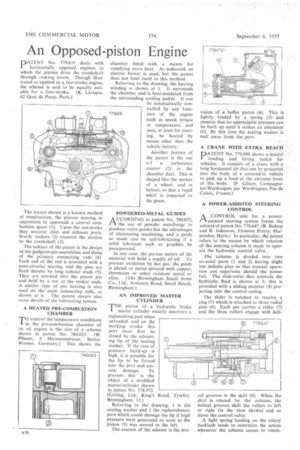
DATENT No. 779,631 deals with
horizontally opposed engines in which the pistons drive the crankshaft through rocking levers. Though illustrated as applied to a two-stroke engine, the scheme is said to be equally suitable for a four-stroke. (R. Laraque, 42 Quai de Passy, Paris.) The layout shown is a known method of construction, the pistons moving in opposition to approach a central combustion space (I). Upon the out-stroke they uncover inlet and exhaust ports. Sturdy rockers (2) transmit the motion to the crankshaft (3).
The subject of the patent is the design of the gudgeon-pin assemblies, and those of the primary connecting rods (4) Each end of the rod is provided with a semi-circular seating, and the pins are fixed thereto by long tubular studs (5). They are screwed into the piston pin and held by a nut at the rocker ends. A similar type of pin bearing is also used on the main connecting rods, as shown at 6. The patent covers also some details of the lubricating system.
A HEATED PRE-COMBUSTION CHAMBER
TO control the temperature conditions in the pre-combustion chamber of an oil engine is the aim of a scheme shown in patent No. 780,023. (W. Pflaum, 9 Herrnannstrasse, Berl inWansee, Germany.) This shows the
chamber fitted with a means for supplying extra heat. As indicated, an electric heater is used, but the patent does not limit itself to this method.
Referring to the drawing, the heating winding is shown at I. It surrounds the chamber and is heat-insulated from the surrounding cooling jacket. It can he automatically controlled by any function of the engine such as speed, torque or temperature, and may, at least for starting, be heated by means other than the vehicle battery."
Another feature of the patent is the use o f a turbulence creator (2) in the chamber duct. This is shaped like the spokes of a wheel, and is helical; so that a rapid whirl is imparted to the gases.
POWDERED-METAL GUIDES A CCORDING to patent No. 780,073, t1 the use of powder metallurgy to produce valve guides has the advantages of eliminating machining, and a guide so made can be self-lubricating if a solid lubricant such as graphite be incorporated.
In any case, the porous nature of the material will hold a supply of oil. To prevent oxidation by hot gas, the guide is plated or metal-sprayed with copper, chromium or other resistant metal or alloy. (The Birmingham Small Arms Co., Ltd., Armoury Road, Small Heath, Birmingham.) AN IMPROVED MASTER CYLINDER
THEpiston of a hydraulic brake master cylinder usually uncovers a replenishing port when unloaded, and on the working stroke this port must first be closed by the advancing lip of the sealing washer. If the rate of pressure build-up is high, it is possible for the lip to be forced into the port and sustain damage. To prevent this is the object of a modified master-cylinder shown in patent No. 778,972. (Girling, Ltd., King's Birmingham, 11.)
Referring to the drawing, 1 is the sealing washer and 2 the replenishment port which could damage the lip if high pressure were generated as soon as the piston (3) was moved to the left.
The essence of the scheme is the pro
Road, Tyseley, vision of a buffer piston (4). This is lightly loaded by a spring (5) and ensures that no appreciable pressure can be built up until it strikes an abutment (6). By this time the sealing washer is well away from the_port.
A CRANE WITH EXTRA REACH
PATENT No. 779,090 shows a, special loading and lifting tackle for vehicles. It consists of a crane with a long horizontal jib that can be projected into the body of a covered-in vehicle to pick up a load at the extreme front of the body. (P. Gilson, Campagnelez-Wardreques par Wardreques, Pas de Calais, France.)
A POWER-ASSISTED STEERING CONTROL
A CONTROL unit for a powerr-lassisted steering system forms the subject of patent No. 779,647. (R. Bishop and R. Johnston, Flowton Priory, Harpenden, Herts.) In particular, the patent refers to the means by which rotation of the steering column is made to operate the hydraulic control valve.
The column is 'divided into two co-axial parts (1 and 2) having slight but definite play so that manual operation can supervene should the power fail. The slide-valve that controls the hydraulic fluid is shown at 3; this is provided with a sliding member (4) projecting into the control casing.
The glider is notched to receive a ring (5) which is attached to three radial pins (6). Each pin carries a roller (7) and the three rollers engage with heli cal grooves in the skirt (8). When the skirt is rotated by the column, the helical grooves shift the rollers to left or right (in the view shown) and so move the control valve.
A light spring loading on the rotary backlash tends to centralize the action whenever the column ceases to rotate.