


DRIVING OF WORMS FOR SIX—WHEELERS.
Page 62
If you've noticed an error in this article please click here to report it so we can fix it.
A Resume of Recently Published Patent Specifications.
T"•apecification of. Charles Kearns Edwards and the Associated "Equipment Co., Ltd., No. 275,020, describes Means for driving the two tandem-wise .wurins necessary in that class of six-wheeler where both pairs of rear wheels are used as drivers, an besides driving them to insert a differential gear. in the drive, so that one pair of driving wheels. can revolve faster, or slower than the other. This arrangement is quite independent of any differential gear situated within either of the axles.
The shaft leading from the gearbox towards the worms terminates in a universal coupling, half of which forms the outer easing of a differential gear and carries with it
the intermediatridnions. Through this differential gear Passes a shaft which carries one of the side wheels of the differential, the other being carried on a sleeve. This sleeve is connected by means of splines to the sleeve which carries the nearer ofthe two worms, the farther one being carried by the shaft which passes through the sleeve. In this manner a differential drive is transmitted to both the rearmost axles. A cardan shaft and two universal couplings are Shown between the two worms.
A New Type of Gear Tooth and the Method of Producing It.
A NAME already well known in connection with toothed 'gearing appears in specification No. 274,667, David Drown and Sons, Ltd., and Henry Edward Merritt. The navel feature of the gears is that part of the operating surface of each tooth is formed by the generating action of' a cutter, whilst the remainder of the tooth is left in a straight line as formed by the cutter, but without any such action. The generation of a tooth with a curved
face from a cutter with . a flat or straight face is well known, but as usually carried out the cutter is allowed to con tinue its generat ing, action, which usually results in the flank of the tooth being weakerred by the movement of the cutter and of the wheel being cut.
In the present case the cutter, which is • represented by a shaded Part in two of the views, revolves at the same peripheral speed, taken at the pitch line, as the wheel to he cut, until the position shown in the :upper views is" reached, when the generating movement is stepped-and the . remainder of the face of the tooth is left" in the form of a straight line.
A' Device which is Said to Reduce_ Skidding THE specification of Harry Stopford, No. 275,087, describes a device which is said to reduce the liability of a vehicle to skid, either • when driving or when the front brakes are applied,.. As will be seen. from the illustration, the rear springs are mounted on slotted brackets, so that they cannot transmit the forward drive of the rear wheels. A substantial push-rod is mounted on each side -of the ehassis, thus the forward drive of the rear wheels is transmitted to an abutment.. which dependsfrom the front
end of the frame. this means the vehicle is pushed along at its front end by the push-rod. The front springs,
being mounted in the same manlier, have no.direct'retarding effect when their brakes are applied, the retarding .effect being transmitted through the push-rods to the abutment shown at the rear of the frame. The inventor claims that by this means the liability to skid is reduced. We cannot, however, follow his reasoning. The abutments being integral with the frame it would appear to us that it is immaterial to which of them the force is transmitted.
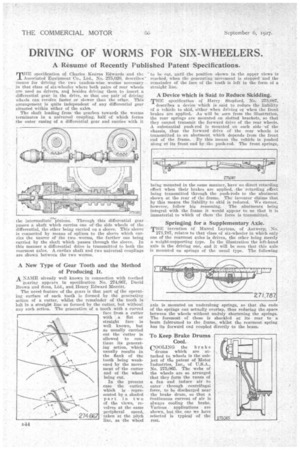
Springing for a Supplementary Axle.
THE invention Of Marcel Leytens, of Antwerp, No.
271,787, 'relates to that class of six-wheeler in which only one of the rearmost axles is driven, the other being merely a weight-supporting type. In the illustration the left-hand axle is the driving one, and it will be seen that this axle is mounted on springs of the usual type. The fallowing
axle is mounted on underslung springs, so that the ends of the springs can actually overlap, thus reducing the space between the wheels without unduly shortening the springs. The foremost of these is shackled at its rear to a beam fulcrumed to the frame, whilst the rearmost spring has its forwa:rd end coupled directly to the beam.
To Keep Brake Drums Cool.
COOLING the brake
drums which are attached to wheels is the subject of .tN patent of Motor Industries, Inc., of U.S.A., No. 275,065. The webs of the wheels are so arranged that they form the vanes of a fan and induce air to enter through centrifugal force, to be discharged near the brake drum, so that a continuous current of air is always cooling the brake. Various applications are shown, but tbe, one we have selected is typical of the rest.