


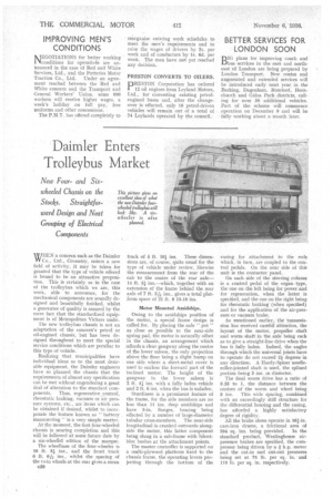
Daimler Enters Troll eybus Market
Page 68
If you've noticed an error in this article please click here to report it so we can fix it.
MIEN a concern such as the Daimler W Co., Ltd., Coventry, enters a new field of activity, it may be taken for granted that the type of vehicle offered is bound to be an attractive proposition, This is certainly so in the case of the trolleybus which we are, this week, able to announce, for the mechanical components are soundly designed and beautifully finished, whilst a guarantee of quality is assured by the mere fact that the standardized equipment is of Metropolitan Vickers make.
The new trolleybus chassis is not an adaptation of the concern's petrol or oil-engined chassis, but has been designed throughout to meet the special service conditions which are peculiar to this type of vehicle.
Realizing that municipalities have individual ideas as to the most desirable equipment, the Daimler engineers have so planned the chassis that the requirements of almost any specification can be met without engendering a great deal of alteration to the standard com ponents. Thus, regenerative . control, rheostatic braking, vacuum or air pressure systems, etc., are items which can be obtained if desired, whilst to incorporate the feature known as "battery manoeuvring" is a very simple matter.
At the moment, the first four-wheeled chassis is nearing completion and this will be followed at some future date by a six-wheered edition of the marque.
The wheelbase of the four-wheeler is 16 ft. 31 ins., and the front track 6 ft. 6* ins., whilst the spacing of the twin wheels at the rear gives a mean c30 track of 5 ft. 101 ins. These dimensions are, of course, quite usual for the type of vehicle under review, likewise the measurement from the rear of the cab to the centre of the rear axle14 ft. 51 ins.—which. together with an extension of the frame behind the rear axle of 7 ft. 3 ins., gives a total platform space of 21 ft. 8 15-16 ins.
Motor Mounted Amidships.
Owing to the amidships position of the motor, a special frame design is called for. By placing the axle " pot " as close as possible to the near-side spring pad; the motor is naturally offset in the chassis, an arrangement which affords a dear gangway along the centre of the lower saloon, the only projection above the floor being a slight hump on one side where a sheet-metal cover is used to enclose the forward part of the inclined motor. The height of the gangway in the lower saloon is 2 ft. 4i ins, with a fully laden vehicle and 2 ft. 6 ins, when the bus is unladen.
Sturdiness is a prominent feature of the frame, for the side members are no less than 11 ins, deep amidships and have 3-in, flanges, bracing being effected by a number of large-diameter tubular cross-members. The near-side longitudinal is cranked outwards alongside the motor, this latter component being slung in a sub-frame with Silentbloc bushes at the attachment points.
The master controller is supported on a multi-plywood platform fixed to the chassis frame, the operating levers projecting through the bottom of the casing for attachment to the rods which, in turn, are coupled to the control pedals. On the near side of this unit is the contactor panel.
On each side of the steering column is a control pedal of the organ type, the one on the left being for power and for regeneration, when the latter is specified, and the one on the right being for rheostatic braking (when specified) and for the application of the air-pressure or vacuum brake.
As mentioned earlier, the transmission has received careful attention, the layout of the motor, propeller shaft and worm shaft in the axle being such as to give a straight-line drive when the bus is fully laden. Indeed, the angles through which the universal joints have to operate do not exceed 21 degrees in any direction. A Hardy-Spicer needleroller-jointed shaft is used, the spliced portion being 3 ins, in diameter.
The final worm drive has a ratio of 9.33 to I, the distance between the centres of the worm and wheel being 8 ins. This wide spacing, combined' with an exceedingly stiff structure for the differential housing and the casing, has afforded a highly satisfactory degree of rigidity.
All the brake shoes operate in 161-in. cast-iron drums, a frictional area of
594 sq. Ins, being provided. In the standard product, Westinghouse airpressure brakes are specified, the compressor being driven by a f h.p. motor and the cut-in and cut-out pressures being set at 75 lb. per sq. in. and 110 lb. per sq. in. respectively.