Flow Testing By Weslake
Page 123

If you've noticed an error in this article please click here to report it so we can fix it.
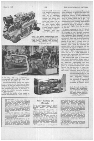
EVOLVED in the early 1920s by Mr. Harry Weslake to investigate variations in the output of identical motorcycle engines, a gasometer" type rig is a special feature of the laboratories of Weslake and Co., Ltd., Rye Harbour, Sussex. This equipment and a blower rig are employed for flow tests of cylinder heads in which air is drawn through the head, or a wooden model.
Tests are repeated with different valve lifts to determine valve-port and combustion-chamber features giving optimum breathing, turbulence characteristics and so on.
Originally applied exclusively to the development of petrol-engine cylinder heads, flow testing has recently been used for evaluating the detailed head features of diesel engines. particularly with regard to modifications necessary for the conversion of units to operate On petrol. These include A.E.C., Bedford. B.M.C. and Rolls-Royce units.
Weslake-modified four-stroke oil engines have successfully run on 80-octane petrol at a b.m.e.p. at least 10 per cent, higher than normal output throughout the range.
War-time and post-war research of vital importance to' the fighting forces and the motor industry included fullscale tests of engines operating on fuels with a high lead. content. These suggested the valve and head modifications necessary to overcome premature failure.
In a typical case an investigation is
made of all the factors that may affect the power output and operational economy of a power unit, including coolant flow, manifold design and exhaust system layouts. Because of the prevalence of faults arising from poor cylinder-head cooling and the formation of hot-spots, cooling-system research is a particularly important part of many Weslake projects.
Test procedure in the development of improved cylinder-head features normally involves a flow test of the original production head, followed by the construction of a wooden model incorporating a number of " obvious " improvements, and a series of tests of modified models.
A swirl meter is located between the, head and the suction pipe to obtain' the rate of air flow and turbulence characteristics.


