


A Pump for Giving Pilot Injection
Page 68
If you've noticed an error in this article please click here to report it so we can fix it.
pATENT N. 682,911 comes from 1 A. B. Volvo, Gothenburg, Sweden, and gives details of an injection Pump
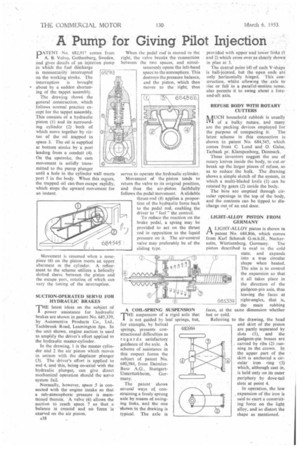
in which the fuel discharge is momentarily interrupted on the working stroke. The interruption is brought • about by a sudden shortening of the. tappet assembly.
The drawing show i the general construction, which follows normal practice except for the tappet assembly. This consists of a hydraulic piston (I) and its surrounding cylinder (2) both of which move together by virtue of the oil trapped in space 3. The oil is supplied at bottom stroke by a port leading from a conduit (4). On the upstroke, the cam movement is solidly transmitted to the pump plunger until a hole in the cylinder wall meets port 5 in the body. When this occurs, the trapped oil can then escape rapidly, which stops the upward movement for an instant.
Movement is resumed when a nosepiece (6) on the piston meets an upper abutment in the cylinder. A. refinement to the scheme utilizes a helically slotted sleeve between the piston and the escape port, rotation of which can vary the timing of the interruption.
SUCTION-OPERATED SERVO FOR HYDRAULIC BRAKES
THE latest ideas on the subject of power assistance for hydraulic brakes are shown in patent No. 685,339, by Automotive Products Co., Ltd., Tachbrook Road, Leamington Spa. In the unit shown, engine suction is used to amplify the driver's effort applied to the hydraulic master-cylinder.
In the drawing, I is the master cylinder arid 2 the air piston which moves in unison with the displacer plunger (3). The driver's effort is applied to rod 4, and this, being co-axial with the hydraulic plunger, can give direct mechanical operation should the servo system fail Normally, however, space 5 is connected with the .engine intake so that a sub-atmospheric pressure is maintained therein. A valve (6) allows the suction to reach space 7 so that a balance is created and no force is exerted on the air piston.
538
When the pedal rod' is moved to the right, the valve breaks the connection between the two spaces, and simultaneously opens the left-hand space to the atmosphere. This destroys the pressure balance, and the piston, which then moves to the right, thus•
serves to operate the hydraulic cylinder.
Movement of the piston tends to return the valve to its original position, and thus the air-piston faithfully follows the pedal movement. Aslidable thrust-rod (8) applies a proportion of the hydraulic force back to the pedal rod, enabling the driver to "fee] " the control.
To reduce the reaction on the brake pedal, a spring may be provided to act on the thrust rod in opposition to the liquid pressure on it. The air-control valve may preferably be of the sliding type.
A COIL-SPRING SUSPENSION
THE suspension of a rigid axle that is not guided by leaf springs, but, for example, by helical springs, presents constructional difficulties as regards satisfactory guidance of the axle. A scheme of assistance in this respect forms the subject of patent No. 680,984, from DaimlerBenz A.G., StuttgartUnterttirkheirn, Germany.
The patent shows several ways of constraining a freely sprung axle by means of swinging links, and the one show n in the drawing is typical. The axle is
provided with upper and low-er links (I and 2) which cross over as clearly shown in plan at 3.
The central point (4) of each V-shape is ball-jointed, bat the open ends are only horizontally hinged. This eon.: struction, whilst allowing the axle to rise or fall in a parallel-motitln sense, also permits it to swing about a foreand-aft axis.
REFUSE BODY WITH ROTARY CUTTERS
hAUCII household rubbish is usually 1V1 of a bulky nature, and many are the packing devices employed for•
the purpose of compacting it. The latest scheme in this connection is shown in patent No. 684,545, which comes from C. Lund and 0, Galse, Tarbaek pr. Klampenborg, Denmark.
These inventors suggest the use of rotary knives inside the body, to cut or break up the larger pieces of refuse, so as to reduce the bulk. The drawing shows a.simple sketch of the system, in which a multi-bladed knife (I) can be rotated by gears (2) inside the body.
The bins are emptied through circular ,openings in the top of the body, and the contents can be tipped to discharge out of an end door.
LIGHT-ALLOY PISTON FROM GERMANY
A LIGHT-ALLOY piston is shown in I-1 patent No. 684,866, which comes from Karl Schmidt G.m.b.H., Neckar
sulm, WOrttemberg, Germany. The piston described is oval in the cold state, and expands into a true circular shape when heated. The aim is to control the expansion so that it all takes place in the direction of the gudgeon-pin axis, thus leaving the faces at right-angles, that is, the main rubbing faces, at the same dimension whether hot or cold.
Referring to the drawing, the head and skirt of the piston are partly separated by slots (1), and the gudgeon-pin bosses are carried by ribs (2) running to the -crown. Io the upper part of the skirt is anchored a circular iron ring • (3) which, although cast in, is held only on its outer periphery by dove-tail slots' at point 4.
In operation, the low expansion of the iron is said to exert a constrieting force on the light alloy, and so distort the shape as mentioned.