


HOW TO CONVERT TO OIL
Page 52
Page 55
If you've noticed an error in this article please click here to report it so we can fix it.
By G. E. Neville
Some Simple Rules to Observe to Ensure Success when Installing an Oil Engine in a Petrol-engined Chassis
ARGELY influenced by economic conditions, operators in increasing numbers are converting serviceable petrol-ertgined chassis to oil fuel. Having decided that the conversion is financially worth while, it is necessary to consider the suitability of the chassis frame and transmission to cope with oil-engine characteristics, the choice of electrical equipment and the likelihood of continuing to enjoy the present advantages of running an oil-engined vehicle.
The reduced running and maintenance costs which normally follow such 'a conversion unquestionably ensure an increase in earning capacity, except where the increased weight of the installation reduces the legal speed of operation. In these circumstances, the operator must make his decision on carefully estimated costs based on the slower operating rate.
Suitability of Chassis
Almost all commercial chassis are suitable for oil engine operation, always provided that the unit selected be reasonably matched to the existing transmission and that the engineer carrying out the conversion is aware of the main pitfalls likely to be encountered. The satisfactory installation of an oil engine involves the accurate planning of enginemovement tendencies and the absorption of the higher engine impulses in such a way that the stresses imposed on the chassis frame and transmission are dispersed as harmlessly as possible.
The suitability of the transmission to cope with the characteristics of the oil engine chosen must first be considered. Provided that the torque of the oil engine is similar to that of the original unit, the transmission system, generally, could safely be expected to give satisfactory service.
Change of Clutch Special attention must, however, be given to the clutch assembly, because the higher impulses of an oil engine impose greater shock loads on the clutch than in a petrol unit of comparable capacity. For this reason the leading makers of clutches greatly derate the capacity of their assemblies when the unit is being used in conjunction with an oil engine. Typical examples are a drop from 170 lb.-ft. to 150 lb.-ft. for a 10-in, clutch, and from 250 1kft. to 210 lb.-ft. for a 12-in. component.
We must, therefore, usually go to a size lamer than was originally 012
fitted. In addition to this, as the higher engine impulses are known to be the cause of frequent failures of the spring-centre type of driven plate, a rigid-centre driven plate is essential.
In dispensing with the springcentre driven plate, however, we have lost a convenient shock absorber between the engine, gearbox and rear axle, and where the vehicle is fitted with mechanical universal joints, some form of insulation is to be recommended. A convenient solution is found in a flexible universal joint, such as the Layrub coupling, the ivind:up characteristics of which provide a useful safeguard. • Non-mechanical universal joints will not usually operate satisfactorily on excessive angles of inclination and care must be exercised to be sure that such increases in angles are within those recommended by the maker.
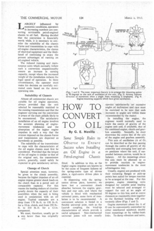
In installing the engine, the engineer would normally need to know the centre of gravity of the engine unit and, if available, that of the combined engine, clutch and gearbox assembly. Secondly, he must determine the centre line of the axis of the engine and gearbox assembly.
This axis of oscillation (A of 0) can be described as the line passing through the centre of gravity of the assembly and emerging fore and aft on positions where the unit, if suspended between centres, would be in balance. All the mountings about this axis must be planned so as to provide reaction to enginemovement tendencies in the most advantageous way.
Usually, engines are produced with their mounting flanges or pick-up points best suited for torque reaction to be arranged at the rear. For this purpose, engine mounting units designed for suitable axial loading must be selected and arranged to support the unit at an angle of 90 degrees to this line, and at centre distances as reasonably close together as the flywheel housing will conveniently allow (Figs. 1 and 2).
Engine movement about the A of 0 Can be conveniently controlled by either interleaved sandwich double front mountings or by rubber-bush links. To damp vibration and noise,
which would otherwise be transmitted to the chassis frame, these mountings must be arranged radially to the point ot emergence of the A of 0 (Fig. 2).
This preference for a double radial front mounting, as compared with the more economical single. mounting (Fig. 3), is further influenced by the fact that, with a ladenvehicle, initial clutch engagement, if severe, can cause a greater tendency for the unit to rock, the resistance of the propeller-shaft movement causing the engine to turn in the direction. opposite to flywheel rotation. In these circumstances, the front mounting acts as, a fulcrum point and some temporary clutch snatch is produced.
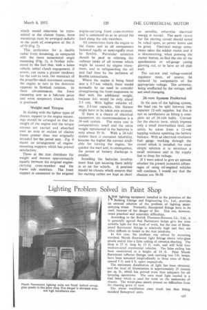
Weight and Torque In dealing with the lighter types of chassis, support to the engine mountings should be arranged so that the weight of the engine and the torque stresses are carried and absorbed over an area or section of chassis frame greater than was originally intended for the petrol unit. Fig. 4, shows an arrangement of enginemounting supports which has proved satisfactory.
Those at the rear distribute the weight and stresses approximately equally between the original enginecarrying cross-member and the frame side members. The front support is. connected to the original engine-carrying front cross-member and is continued so as to spread the load along the side members.
All connections from the engine to the frame and to all components fastened rigidly or semiJrigidly must be flexible. Particular attention should be paid to relieving the radiator tanks of all stresses which, might be caused by engine movement, and to safeguarding the oil and fuel lines by the inclusion of flexible connections.
Where the engine is being fitted into a 5-7-ton vehicle, there would. normally be no need to consider strengthening the front suspension to deal with the additional weight, because this would_ be only about 2-3 cwt. With lighter vehicles of, say, 2-3-ton capacity,. this feature might have to be taken into account.
If there is a choice of electrical equipment, my recommendation is a.
24-volt system. The extra cost Is comparatively small and the extra weight represented in the batteries is Only about 50 lb. With a 24-volt system there is increased reliability, because the higher the current available for turning the engine, the quicker the start and, in consequence, the period of battery discharge is smaller.
Installing the batteries involves more than just securing them safely in or on the vehicle. A position. should be chosen which ensures that the starting cables are kept as short as possible, otherwise electrical energy is wasted. The earth return for the starting circuit should never be relied upon, as power losses can
be great. Electrical energy sometimes takes the oddest routes and it is disconcerting, when pressing the starter button, to find the rim of the speedometer or oil-gauge casing glowing red, or to have an oil pipe melt.
The cut-out and. voltage-control regulator must, of course, be replaced by components of the appropriate voltage. The ammeter,, being unaffected by the voltage, will not need changing.
24-volt System Preferred In the case of the lighting system, the load can be split between two separate 12-volt supplies, but this is not so satisfactory as fitting a complete set of 24-volt bulbs. Current for the electric horn, which imposes only a small intermediate load, can safely be taken from a 12-volt tapping without upsetting the battery balance. With an electrical-resistance fuel gauge working through the circuit which is installed, the most simple solution is to introduce a small resistance unit in the supply line to drop the voltage.
If I were asked to give an opinion whether the present economic advantages of using oil:engined vehicles will continue, I would say that the chances are 50-50.