


A Power transmitting Trailer. Coupling
Page 50
If you've noticed an error in this article please click here to report it so we can fix it.
A Resum4 of Patent Specifications That Have Recently Been Published
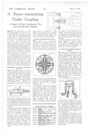
DATE.NT No. 441,4% shows a trailer I coupling whiCh serves not only as a towing connection, but also contains a drive shaft for transmitting power to the trailer. The patentees are John Fowler and Co. (Leeds), Ltd., and N. C. Store, 13, Leathley Road, Huns let, Leeds: In the drawing, which shows a plan view, the tractor has a rearward extension carrying a gimbal ring pivoted horizontally on pins (1) and carrying the towing connection (3) which is vertically pivoted abOut axis 5. The drive is transmitted by internal splined shafts, carrying two universal joints, the centres of which are coaxial with• the pivots (4 and 5). An Interesting feature is the coupling of the gimbal : ring (2) with the towing connection (3) by means of two toothed sectors (6 and 7). This feature ensures that whatever angular deviation may exist between the two vehicles', it will be evenly shared between the two internal universal joints.
Modifications to Oil-engine Combustion Systems.
THE name Franz Lang, 41, Laimerstrasse, Mimich, Germany, is already known in the 'oil-engine world in connection With the Lanova combustion system; and thisinventor describes, in patent No. 1 441,675, some further developments in the design of oil-engine combuStion systems. Whereas the usual position for the heater ping is substantially in the path of the fuel
spray, in the proposed scheme it is located in an offset position to one side of the passage connecting the air cell with the cylinder. When placed here, it is claimed, the life of the heater is increased, whilst starting is in no way impaired.
A further point is the arrangement of the dual air-cell system. Hitherto, an air cell (1) has had an extension (2) which can be segregated by a sliding valve (3). This valve was closed for starting, so that a temporary higher compression was produced ; during normal running the valve was opened and both chambers were in action. According to the present invention the foregoing procedure is exactly reversed, the two chambers being used only for starting, whilst normal run 1340
ning makes use of chamber 1. This practice, the inventor states, considerably facilitates starting, owing to the lower mechanical effort required to overcome the reduced compression.
Automatic Injection Pump Advance.
THE design of a centrifugally operated injection-advance mechanism is not so simple as might at first appear, mainly on account of the high torque IranSmitted, and because of the imperative need for absence of backlash. Patent No. 441,125 shows a
design in which due consideration has been given to the foregoing points; the inventor is P. Belyavin, 2, Purcell Mansions, Queen's Club Gardens, London, W.14.
The device is made in the form of two face-Ito-face discs, one of which carries two abutments (2), whilst the other has mounted upon it two similar abutments (1). The torque is transmitted from one set to the other by compression on rollers (3) carried in radially sliding bob-weights (4), of which four are provided. In operation, centrifugal force urges the weights outwards, which movement forces the abutments angularly apart;
this refers to the upper and lower weights. Those shown to the left and the right serve the purpose of preventing .backlash, the abutment faces in this case being sloped in the opposite direction.
The four weights may be linked or geared together to ensure uniform action, whilst to oppose the squarelaw increase in centrifugal force, the springs (5) are three in number, and come into action successively.
An Interesting Variable-compression Engine.
improve the volumetric efficiency
of an engine by providing a compression ratio adjusted to suit prevailing conditions is the object of the scheme shown in patent No. 441,666, by L. de Monge. 11, Rue des Damattes a Puteaux, Seine, France. To achieve this end it-is proposed to vary the value of the compression by controlling the
height of the piston ascent. The accompanying drawing shows one method of carrying out the scheme. In this the piston has a number of lengthwise slots (1) in its skirt, into which lngs (2), carried by a bevel gear,-project. This gear can be rotated by pinion on shaft 3 and, in consequence, rotates the piston.
The connecting rod is made in two portions screwed together, so that rotation Of the piston lengthens or shortens the rod, and thus alters the compression. Whilst the length of thread on the connecting rod appears to be generous, experience goes to prove that unlocked screw threads do not possess much durability when subjected to a hammering action.
A universally jointed small end enables variations in compression ratio to be made while the engine is running. This additional mechanism will necessarily increase the weight of the reciprocating parts, which is obviously undesirable, but the gain in ow main respect may compensate for this slight disadvantage.