


HINTS ON MAINTENANCE.
Page 26
Page 27
If you've noticed an error in this article please click here to report it so we can fix it.
How to' Get the Best Out of a Vehicle, to Secure Reliability and to Avoid Trouble.
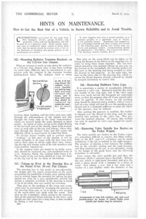
342.—Mounting Radiator Trunnion Brackets cn the 2-2i-ton Guy Chassis.: When an attempt is made to take down the radiator of a 2-21-ton Guy chassis after it has been working for some time, difficulty may be encountered in connection with the removal of the trunnion bracket holding-down bolts. The radiator itself is 'slung
between these brackets, and the bolts used pass right through the side.members of the chassis and also through the front ends of the front cross-member, which are, secured inside the main channels at these points. In course of time, owing to the slight flexing of the forward end of the chassis, these bolts become worn at each side at the top and bottom, where they pass through the channel webs, and this causes the difficulty which is experienced in removing them.
To obviate future trouble and to prevent undue 1working " of this part of the chassis, it will be found advisable to do away with the four long bolts and in their place to utilize eight short ones, clamping the tep and bottom webs of the side members and cross-member respectively.
If the original bolts are found to be badly worn, they should be reamered out, and machined bolts of -4-in. diameter fitted, the original bolts being in. The length of the new bolts should be P. ins, for those at the top and 1-11 ins, for those at the bottom.
343.—Taking up Wear in the Steering Box of the Model 15-ter. 30-cwt. Fiat Chassis.
The steering box in this model is non-adjustable, the design and the ample proportions of the parts precluding the possibility of undue wear taking place, and in normal usage the necessity for taking up play should not arise for a very considerable period, but during a complete overhaul, if the steering is found to be at all slack, this can readily be overcome.
Thus play in the meshing of the worm and wormwheel may be prevented by reversing the position of the steering drop arm, se as to bring a new portion of the worm-wheel into mesh with the worm. End play on the wormshaft, which, owing to the construction of the grooved thrust bearing at the lower end, should not take place for a long time, is best rectified by fitting a new bearing.
B42 Side play on the worm-wheel can be taken up by facing the flanges of the halves of the steering box, in order to bring them closer together. The last-mentioned operation also permits taking up any play on the journal of the wormshaft, the bearing surface for this part in the steering box being scraped to allow the journal to bed properly. At the same time, the bore at the lower end of the steering box, which receives the thrust bearing already referred to, should be scraped accurately to receive this. •
344.—Removing Stubborn Valve Caps.
It is sometimes a matter of considerable difficulty to unscrew a valve cup. Spanners used for this work are usually of the ring type, and if the valve caps have yen much service the hexagons are sometimes worn, so that the spanner slips off if any considerable force be applied. If this occurs, an old sparking plug should be obtained and a washer, with a central, hole of a size which will just fit over the sparking plug thread and of a diameter sufficient to cover the whole of the spanner, may be utilized.
After putting the spanner in position, the washer is slipped over the thread of the plug, and the plug screwed into position in the valve cap. This prevents the spanner slipping. Of course, this method can only be applied on valve caps tapped for sparking plugs.
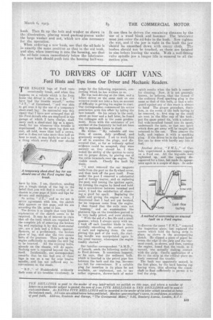
345.—Removing Valve Spindle Jaw Bushes on the Foden Wagon.
The valve spindle jaw bushes on the Foden wagon are sometimes difficult to remove, but these bushes, both on the H.P. and LP. cylinders, can be easily withdrawn if the job is tackled in the right manner. The practice of placing a bolt between the stuffingbox on the cylinder casting and the bush housing, and then unscrewing the nut, is not advisable, owing to the design of the guide bars, and the following procedure is advisable.: First remove the valve spindle jaw and then the lubricator which is situated above the bush. Release the nut, which is right-hand threaded, and give the bush a sharp knock with a hammer or a piece of wood. Now obtain a i-in. bolt 6 ins, long and a washer of a, size slightly under the diameter of the bush. Then fit up the bolt and washer as shown in the illustration, placing wood packing-pieces under the large washer and nut, which are also necessary for thc operation.
When ordering a new bush, see that the oil-hole is in exactly the same position as that in the old bush, and also, when inserting it into the housing, see that the oil-hole comes immediately below the lubricator. A new bush should push into the housing half-way. It can then be driven the remaining distance by the use of a wood block and hammer The lubricator must just enter the zil-hole in the bush. Now tighten the nut, and if the jaw is tight in the bush the jaw should be smoothed down with emery cloth. The bushes should not be touched, as these are finished to size before leaving the works. -With a well-fitting valve spindle jaw a longer life is ensured to all the motion pins.