


New Maxvvell box: step-by-step guide
Page 23
If you've noticed an error in this article please click here to report it so we can fix it.
[HE NEW Maxwell bus gearbox see p23) announced this week s a multi-layshaft design, with :he first production model havn g four layshafts grouped iround the input shaft.
Each layshaft has its own nultiplate pneumatic clutch, and iccess to these clutches for sereicing is via end covers which illow individual clutch assemflies to be replaced without the ieed of removing or stripping he gearbox.
The gearbox ratios are seleced by these clutches, under the ontrol of a switch acting hrough an electronic control init and an electro-pneumatic alve.
The designed torque capacity the Maxwell gearbox is 00Nm (650 Ibft), and a retarder inction is incorporated which ives simultaneous partial enagement of the first and second ear clutches when the vehicle is third or fourth gear.
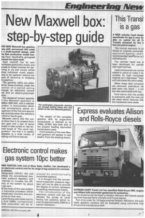
Maxwell claims that the outut drive line in its present form ;pur gear and a pair of spiral evels) is best suited to rear-enined buses of "the usual conguration" but that it is readily daptable to a wide variety of xisting and future layouts. The weight of the complete gearbox with its angle-drive components is claimed to be 144kg (3191b) less than that of the present leading equivalent transmission pack.
A full analysis of the new Maxwell gearbox will appear in next week's From the drawing board.