 1
1 2
2 3
3 4
4 5
5 6
6 7
7 8
8 9
9 10
10 11
11 12
12 13
13 14
14 15
15 16
16 17
17 18
18 19
19 20
20 21
21 22
22 23
23 24
24 25
25 26
26 27
27 28
28 29
29 30
30 31
31 32
32 33
33 34
34 35
35 36
36 37
37 38
38 39
39 40
40 41
41 42
42 43
43 44
44 45
45 46
46 47
47 48
48 49
49 50
50 51
51 52
52 53
53 54
54 55
55 56
56 57
57 58
58 59
59 60
60 61
61 62
62 63
63 64
64 65
65 66
66 67
67 68
68 69
69 70
70 71
71 72
72 73
73 74
74 75
75 76
76 77
77 78
78 79
79 80
80 81
81 82
82 83
83 84
84 85
85 86
86 87
87 88
88 89
89 90
90 91
91 92
92 93
93 94
94 95
95 96
96 97
97 98
98 99
99 100
100 101
101 102
102 103
103 104
104 105
105 106
106 107
107 108
108 109
109 110
110 111
111 112
112 113
113 114
114 115
115 116
116 117
117 118
118 119
119 120
120 121
121 122
122 123
123 124
124 125
125 126
126 127
127 128
128 129
129 130
130 131
131 132
132 133
133 134
134 135
135 136
136 Sprung Wheels
Page 100
If you've noticed an error in this article please click here to report it so we can fix it.
I NCORPORATION of a suspension system inside wheels is a subject that has appealed to inventors since the earliest days of motor vehicles, and many varied schemes have been proposed in the past. With the advent of the modern methods of bonding rubber to metal, however, methods hitherto impracticable are now possible, and a scheme based on rubber bonding forms the subject of patent No. 792,302. (A. Mantzel, Forststrasse 74, Stuttgart-W., Germany.)
Referring to the drawing, the hub carries a guide disc (1) which is embraced by a pair of flanges (2) on the hub. The function of theses parts is to restrain the movement of the rim to one plane. The guide disc is fitted with a low-friction envelope (3) to avoid heat generation.
The springs consist of rubber rings (4 and 5) of conical outline, bonded to both the hub and the rim members. The small diameter of the left-hand rubber ring enables the brake-drum to be located outside it. To prevent metal-to-metal contact at the extremity of deflection, a rubber ring (6) surrounds the hub ring.
HYDRO-PNEUMATIC FRONTWHEEL SUSPENSION PATENT No. 792,310 shows a suspension system in which air is used for the spring, but it is contained in a separate reservoir remote from the axle. The connection is made by hydraulic
means. (Ford Motor Co., Ltd., 88 Regent Street, London, W.I.) The wheel is located by a single swinging link (1) which is pivoted on a shaft (2) carried in bearings on a front crossmember (3). The load is supported by a telescopic unit (4) resembling a shockabsorber, but the liquid displaced by deflection is led through a pipe (5) to the spring unit.
This comprises a small lower cylinder (6) which receives the liquid and an enlarged upper cylinder (7) containing air. The pistons are interconnected by a rod.
The general level of the suspension can be varied by adding or removing liquid from the hydraulic system, and a pump (8) is fitted to provide hydraulic pressure. A manually operated valve (9) controls this function, and when not in use, allows the pump to be by-passed.
A PILOT-INJECTION SCHEME TO inject a small fuel charge in advance of the main delivery is a well-known practice in oil engines, but, even so, it is difficult to eliminate a high peak of cylinder pressure when the main charge commences. A scheme in which the main injection is delayed until the cylinder pressure has risen to a mid-value is shown in patent No. 792,775. The term " mid-value "'refers to the mean between the maximum and minimum working
pressures. (E. Satzger, 6 Am Tabor Vienna II, Austria.) For this condition to be satisfied it is necessary for the fuel injector to be controlled by the cylinder pressure and the drawing shows diagrammatically how this is done.
Fuel from the injection pump enters at 1 and by•foreing open a spring-loaded valve (2) passes through the nozzle (3) into the combustion space. This gives the pilot injection. The pressure of the fuel is also applied to an adjoining chamber containing a cylindrical valve (4) which closes off the main injection nozzle. (5).
This valve is closed by a spring (6) and does not open with the fuel pressure because there is no area for it to act upon.
It can, however, be opened by cylinder pressure and does so when the gas pressure overcomes the spring. The bottom of the larger valve is made concave as shown to provide an effective area for the compression to work upon.
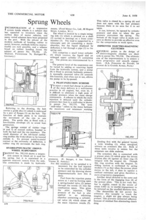
IMPROVED ELECTRO-MAGNETIC CLUTCHES
QEVERAL points in the design of
• electro-magnetic clutches are dealt with in patent No. 792,530. The ultimate aim of the improvements is to ensure a more progressive and smooth engagement. (S.A. Francaise do Ferodo, 64 Avenue de la Grande Armee, Paris.) Dealing first with the general layout, a tonic winding (1), when energized, attracts an armature disc (2). Both of these units revolve in unison but the armature can slide endwise.
The armature disc is connected with a presser plate (3) which grips the driven friction disc (4) against an inner ring (5) integral with the magnet (6). Though this ring revolves with the magnet, its sliding motion is cushioned by spring washers (7) so that when the presser plate moves to the left, if does so against a resilient resistance and gives therefore a more progressive engagement.
Another detail directed to the same end is the form of the engaging face (8) of the presser plate. This is not truly flat, but is slightly coned to the extent of about 0.002 in. to 'enable engagement to be initiated' on the smallest diameter first.
The dimensions do not permit the armature disc actually to touch the magnet, a slight air gap always being present. This prevents unwanted adhesion because of residual flux eliminating clutch drag.