


OVERHAULING THE BRISTOL,
Page 22
Page 23
Page 24
Page 25
If you've noticed an error in this article please click here to report it so we can fix it.
No. 21.—A 4-ton Chassis of Remarkably Simple Construction, Combining Ease of Adjustment with 'Pronounced Accessibility.
THE BRISTOL chassis is a fine example of the vehicle, which is built as the result of many years' experience in running motor vehicles of various makes. It is constructed to fulfil the conditions of freedom from breakdown, ease of
repaiz and general efficiency. That these objects have been attained is
shown by the successful operation of a large fleet of Bristol vehicles by the builders. Every part of the vehicle has been designed from the i
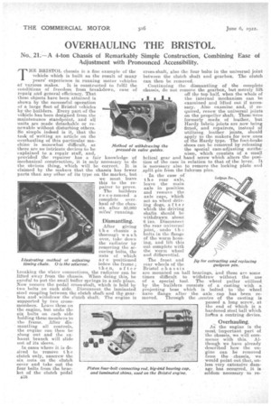
maintenance standpoint, and all units are made detachable or re newable without disturbing others. So simple indeed is it., that the task of writing an article' on the overhauling of this particular ma chine is somewhat difficult, as Method of withdrawing the there are no intricate devices to be pressed-in valve guides. explained to a repair staff, and, provided the repairer has a fair knowledge of mechanical construction, it is only necessary to do the obvious thing, which will be correct. It is claimed by the makers that the chassis has fewer parts than any other of its type on the market, but we must leave this to the repairer to prove.
The builders recommend a complete overhaul of the chassis. after 50,000 miles' running: ,Dismantling.
After giving t h e chassis' a thorough wash over, take down the radiator by removing the securing bolts, the nuts of which a r e positioned below the frame ; then, after breaking the W-ater connections, the radiator can be lifted away from the chassis. When doing this, be careful to put the small buffer springs in a safe place. Now remove the pedal cross-shaft, which is held by two bolts on each side. Disconnect the laminated steel coupling between the clutch shaft and the gearbox and withdraw the clutch shaft. The engine is supported by two crossmembers. Leave these on the engine, but undo the six bolts on each side holding these members to .the frame. After dismantling all controls, the engine can then be slung out and the exhaust branch will slide out of its sleeve.
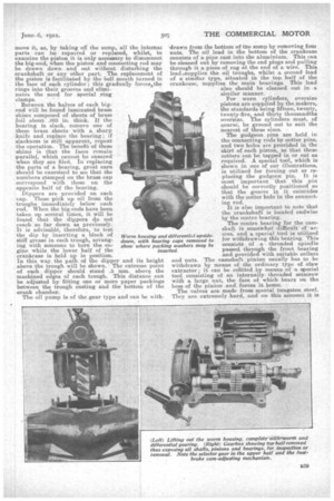
ilustrating method of adjusting timing chain. 0 is the setscrew.
In cases where it is desired to remove t h e clutch only, unscrew the six, nuts on the clutch cover and take out the four bolts from the bracket of the clutch pedal
n38 cross-shaft, also the four bolts in the universal joint between the clutch shaft and gearbox. The clutch can then be removed.
Continuing the dismantling of the complete chassis, do not remove the gearbox, but merely lift
off the top half, when the whole of the internal mechanism can be examined and lifted out if necessary. Also examine and, if required, renew the universal joints on the propeller shaft. These were formerly made of leather, but Hardy fabric joints are now being fitted, and repairers, instead of utilizing, leather joints, should apply to the makers for new ones of the Hardy type. The foot-brake shoes can be removed by releasing the special cam-adjusting mechanism, which consists of a small helical gear and hand screw which alters the position of the cam in relation to that of the lever. It is necessary also to remove the locking plate and _split pin from the fulcrum pins..
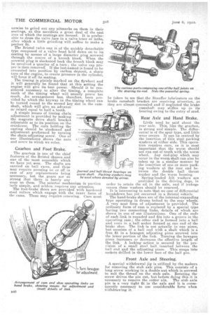
In the case of the rear axle, leave the main axle in position and remove the axle caps, which act as wheel driving dogs, after which the driving shafts should be withdrawn about 6 ins. Disconnect. the rear universal joint, undo t h bolts in the flange of the worm housing, and lift this out complete with and differential. the worm wheel The front and rear wheels of the Bristol chassis are mounted on ball bearings, and these are some times difficult to withdraw without the use of a special tool. The wheel puller utilized by the builders consists of a casting with a projecting boss which is bolted to the wheel nave flange after the axle cap has been removed. Through the .centre of the casting is passed a long screw, at the end of which is a hardened steel ball which foilns a centring device.
Gudgeon Pin
Jig for extracting and replacing gudgeon pin.
, Overhauling.
AS' the engine is the most, important part of the chassis, we will commence with this. Altho.u0 we have already described how the engine can be removed from the chassis, we would point out that, unless very extensive damage. has . occurred, it is seldomnecessary • to re move it, as, by taking off the sump, all the internal parts can be repaired or replaced, whilst, to examine the piston it is only necessary to disconnect the big-end, when the piston and connecting rod may be drawn down and out without disturbing the crankshaft or any other part. The replacement of the piston is facilitated by the bell mouth turned in the face of each cylinder ; this gradually forces the rings into their grooves and eliminates the need for special ring clamps.
Between the halves of each bigend will be found laminated brass shims composed of sheets of brass foil about .003 in. thick. If the bearing is slack, remove one of these brass sheets with a sharp knife and replace the bearing ; if slackness is still apparent, repeat the operation. The benefit of these shims is that the faces remain parallel, which cannot be ensured when they are filed. In replacing the parts of a bearing, great care should be exercised to see that the numbers stamped on the brass cap correspond with those on the opposite half of the bearing.
Dippers are provided on each cap. These pick up oil from the troughs immediately below each rod. When the big-ends have been taken up several times, it will be found that the dippers do not reach so far down as previously. It is advisable, therefore, to test the dip by inserting a block of stiff grease in each trough, arranging with someone to turn the engine while the lower half of the crankcase is held up in position. In this way the path of the dipper and its height above the trough will be shown. The extreme point of each dipper should stand .6 mm. above the machined edges of each trough. This distance can be adjusted by fitting one or more paper packings between the trough casting and the bottom of the crank chamber.
The oil pump is of the gear type and can be with
-drawn from the bottom of the sump by removing foul nuts. The oil lead in the bottom_ of the crankcase consists of a pipe cast into the aluminium. This can be cleaned out by removing the end plugs and pulling through it a piece of rag at the end of a wire. This, lead .sup p lies the oil troughs, whilst a second lead of a similar type, situated in the top half of the crankcase, supplies the main bearings. This lead also should be cleaned out in a similar manner.
For worn cylinders, oversize pistons are supplied by the.makers, the standards being fifteen, twenty, twenty-five, and thirty thousandths oveistze. The cylinders must, of course, be ground out to suit the nearest of these sizes.
The gudgeon pins are held in the connecting rods by cotter pins, and two holes are provided in the skirt of each piston so that these cotters can be tapped in or out as required. A special tool, which is shown in one of our illustrations, is utilized for forcing out or replacing the gudgeon pin. It is most important that this pin should be correctly positioned so that the groove in it coincides with the cotter hole in the connecting rod. It is also important to note that the crankshaft is located endwise by the centre bearing.
The centre bearing for the camshaft is somewhat difficult' of access, and a special tool is utilized for withdrawing this bearing. This consists of a threaded spindle passed through the front bearing and provided with suitable collars and nuts. The -camshaft pinion usually has to be withdrawn by means of the ordinary type of claw extractor ; it can be refitted by means of a special tool consisting of an internally. threaded setscrew with a. large nut, the •face of which bears on the boss of the pinion and forces it home. The valves are made from special tungsten steel. They are extremely hard, and on this account it is unwise to grind out any pitmarks on them in their seatings, as this sacrifices a great deal of the cast iron of which the seatings are formed. It is preferable to dress the valve face in a valve truer or lathe, after which a little grinding will, suffice to make a perfect fit.
The Bristol valve cap is of the quickly detachable type composed of a valve head held down on to its seating by means of a large diameter plug screwed through the centre of a breech block. When the screwed plug is slackened back the breech block may be revolved a quarter of a turn ; the valve cap proper is then removed! If the last-named is found to be cemented into position by carbon deposit, a sharp turn of the engine, to create pressure in the cylinder, will force it 'off its seating. The timing is plainly marked on the flywheel and it will generally be found that at this setting the engine will give its best power. Should it be considered necessary to alter the timing, a complete tooth of the timing wheel will usually prove too much. An arrangement has, therefore, been provided by which the keyway in the timing wheel can be turned round to the second key slot in the camshaft, which will give an advance' or retard equal to half a tooth. A simple means of timing chain adjustment is provided by making the magneto drive shaft bracket adjustable as to its position on the crankcase. The nuts hOlding the casting should be slackened and adjustment performed by turning the chain-adjusting screw. One of our illustrations shows the nuts and screw to which we refer.
Gearbox and Foot' Brake.
The gearbox is one of the chief features of the Bristol chassis and one of the -most accessible which we have yet seen. The shafts are carried on. ball races, and these may require pressing on or off in case of any replacements being necessary, but the gears are so strong that there is barely any wear on them. The selector mechanism is particu larly simple, and seldom requires any attention.
The foot-brake shoes are provided with hardened steel rollers which engage with the inner faces of the cams. Then, may require renewing. Care must
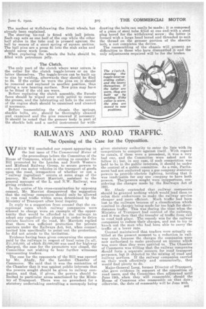
Journal and ball th worm shaft. Pack be used where de
be taken to see that the Stauffer lubricators on the brake camshaft bracket are receiving attention, as they arc almest concealed and if neglected the brake camshaft may stiffen up in its bearing owing to the entry of mud.
Rear Axle and Hand Brake.
Little need be said about the rear axle. This, like the gearbox, is strong and •simple. The differential-is of the spur type, and little wear occurs. It can be centred by the insertion of thin steel packing washers at either side. This operation requires care, as it is most important that the worm should not run out of truth with the worm wheel. Any end-play Which may occur in the worm shaft can also be taken up in a similar manner by the insertion of one or more pack ' ing washers at the rear end between the double ball thrust washer and the Worm housing.
Spring-loaded felt washers are provided in the driving dogs, in order to retain the oil in the axle, and .f leakage occurs these washers should be renewed.
It is interesting to note that no case of differential breakdown has yet occurred in a Bristol vehicle. The hand-brake shoes are of the internal-expanding type operating in drums 'bolted to the rear wheels. A very neat form of adjustment is provided. The ordinary form of cam is replaced by a special type having two connecting links, details of which are shown in one of our illustrations. One of the ends of each link is rounded and fits into a groove in the operating cam; the other end is formed into a ball and rests in a ball socket formed at one end of the brake shoe. The link is not actually in one piece, but consists of a ball end with a shaft which is a free fit in a hexagon adjusting piece screwed into the lower portion of the link. Turning the hexagon piece increases or decreases the effective length of the link. A locking' action is secured by the provision of a small steel ball inserted between the ball end and the adjusting piece. This snaps into sockets drilled in the lower face of the ball pin.
Front Axle and Steering.
A special withdrawal jig is utilized by the makers for removing, the stub axle pins. This consists of a long screw working in a double nut which is screwed to suit the tlaread.on the stub axle. Rotating the screw drives the pin out, but before doing this it is necessary -to remove the cotter pin. The stub axle pin is a very tight fit in the axle and it is consequently necessary to use considerable force when withdrawing it. The method ot -withdrawing, the front wheels has already been explained.
The steering tie-rod is fitted with ball joints. Each cap acts as one half of the cup while the other half slides in the tube and is pressed against the ball by means of a stout spring of square section. The ball pins are a press fit into the stub axles and should never work loose..
When replacing the wheels the hubs should be. filled with petroleum jelly.
The Clutch.
The only part of the clutch where wear occurs is the collar for the clutch toggle-levers or on the latter themselves. The toggle-levers can be built up to size by welding, afterwards they should be filed to fit. If the collar be worn the _pins on it should be removed and replaced in another position, thus giving a new bearing surface. New pins may have to be fitted if the old are worn.
Before replacing the clutch assembly, the Ferodo faces should be wiped over with petrol to remoxe the grease, and the lubricating oil hole in the centre of the engine shaft should be examined and cleaned if necessary.
Before reassembling the chassis the springs, shackle bolts, etc., should be thoroughly cleaned and examined and the pins renewed if necessary. It should be noted that the greaser body is part of the shackle bolt and a useful instrument for with
drawing the bolts can easily be made; it is composed of a piece of steel tube filled at one entiewith a steel plug bored for the withdrawal screw ; the latter is formed with a large head bored and threaded to suit the thread on the greaser portion of the shackle bolt, a nut completes the device. The reassembling of the chassis will present no difficulties to those who have dismantled it and the only adjustments required will be for the brakes.