


A NEW A.E.C.
Page 58
Page 59
Page 60
Page 61
If you've noticed an error in this article please click here to report it so we can fix it.
RENOWN
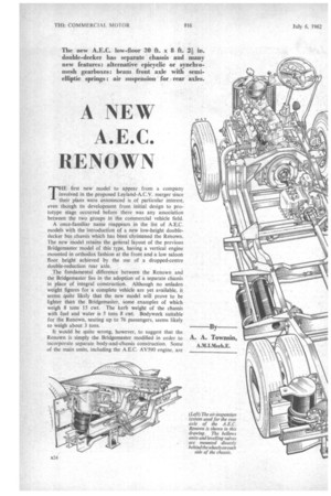
THE first new model to appear from a company involved in the proposed Leyland-A.C.V. merger since their plans were announced is of particular interest, even though its development from initial design to prototype stage occurred before there was any association between the two groups in the commercial vehicle field.
A once-familiar name reappears in the list of A.E.C. models with the introduction of a new low-height doubledecker bus chassis which has been christened the Renown. The new model retains the general layout of the previous Bridgemaster model of this type, having a vertical engine mounted in orthodox fashion at the front and a low saloon floor height achieved by the use of a dropped-centre double-reduction rear axle.
The fundamental difference between the Renown and the Bridgemaster lies in the adoption of a separate chassis in place of integral construction. Although no unladen weight figures for a complete vehicle are yet available, it seems quite likely that the new model will prove to be lighter than the Bridgemaster, some examples of which weigh 8 tons 15 cwt. The kerb weight of the chassis with fuel and water is 5 tons 8 cwt. Bodywork suitable for the Renown, seating up to 76 passengers, seems likely to weigh about 3 tons.
It would be quite wrong, however, to suggest that the Renown is simply the Bridgemaster modified in order to incorporate separate body-and-chassis construction. Some of the main units, including the A.E.C. AV590 engine. are llmost identical, whilst others are similar in principle to hose of the previous model, but there la#s been so cornalete a revision of the specification and layout as to justify -egarding the model as a completely new design.
The probability that a large proportion of operators will wish to fit forward-entrance bodywork has not only been aken into account, but advantage has been taken of it n the design of the transmission.
On the Bridgemaster the transmission line was offset to he left. On the B3RA rear-entrance version it was possible o eliminate transfer gearing, the drive being taken direct :rom the rear of the unit-mounted synchromesh gearbox ay two-piece propeller shaft to the dropped-centre rear axle. A set of transfer gears was added behind the gearbox of the forward-entrance 2B3RA Bridgemaster model to lower the forward end of the propeller shaft. Some intrusion of the gearbox casing and the front sub-frame above the floor level remained, however, whilst the design did not lend itself to use of an epicyclic gearbox as an alternative to the synchromesh unit. The Renown transmission line and frame design reflects an ingenious approach to these problems. The transmission line is offset to the right. To avoid encroaching into the driver's cab unduly, the engine is mounted at an appreciable angle to the chassis centre-line, its front end being to the left and the centre of its flywheel to the right of this line. In addition the engine is inclined downwards to the rear and the cylinder block is arranged to lean slightly to the left, away from the driver.
This layout has enabled a separately mounted epicyclic gearbox to be accommodated partially under the .stairs of a forward-entrance model, and the Renown is accordingly offered with Monocontrol transmission, being designated 3B2RA in this form. A synchromesh gearbox version, model 3B3RA, is also available. In this ease the gearbox is unit-mounted on the rear of the engine. Its position slightly to the right of the chassis centre-line eliminates the need for transfer gearing even with forwardentrance bodywork.
Rear-entrance bodywork can be fitted to the synchromesh chassis without difficulty. The Monocontrol version is not specifically offered for rear-entrance bodywork, although it would not seem impossible to achieve a satisfactory, design of this type with a rearranged lower-deck seating layout.
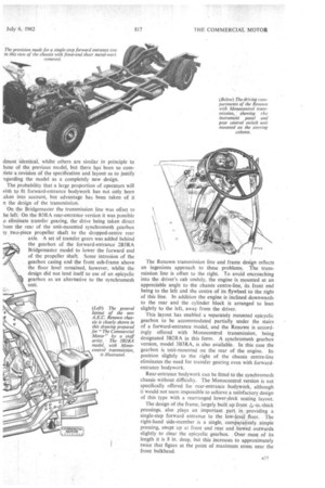
The design of ffie frame, largely built up from is‘-in.-thick pressings, also plays an important . part. in providing a single-step forward entrance to the low-level. floor. The right-hand side-member is a single, comparkively simple pressing, swept up at front and rear and bowed outwards slightly to clear the epicyclic gearbox. Over most of its length it is 8 in. deep, but this increases to approximately twice that figure at the point of maximum stress near the front bulkhead.
As with other models of this layout, the ground-clearance requirements of the P.S.V. (Conditions of Fitness) Regulations have largely determined the design of the left-hand side-member. These prescribe that a ground-clearance of 10 in. must be maintained over a width of one-third of the front-axle track on each side of the vehicle centre-line for a distance of 13 ft. from its 'front end.
The front and rear portions of the left-hand side-member are similar to the right-hand member. To maintain a low step level the main beam strength in the amidships section is provided by an outer member placed approximately 81in. farther from the chassis centre-line than the front portion, but parallel to it. This outer member, built up from two channel-section pressings mounted back to back, has a maximum depth of 8 in. and is attached to the frontend side-member through a malleable casting. Towards the rear of its lowest portion it is bolted to an extended cross-member and one of the channel sections is continued as far as the outrigger of the next cross-member to the rear. Both these are in turn attached to the rear portion of the main side-member.
The transmission layout has enabled a 4-in.-deep intermediate section of the near-side side-member to be incorporated so as to give a high degree of continuity in a fore-and-aft direction.
Channel-section cross-members and outrigger brackets are used throughout. In some cases these have gussets attached to them by welding, but bolted construction is used for all major assemblies. A bridge-shaped cross-member is fitted over the flywheel housing and a channel-section tie braces the frame under this item.
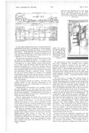
With the vehicle laden the height above ground of the top of the side-members is 19 in. over most of the amidships portion of the chassis. At the forward entrance position this reduces to 15 in. and the mid-portions of the cross-members to the rear of this are shaped to give a height at the centre of the gangway of 16.5 in. The actual floor heights need be only fractionally higher than these.
The Renown's suspension differs considerably from that of the Bridgemaster. Whereas the latter model had independent front suspension of the coil-spring and unequallength-wishbone type, similar to that used on the Routemaster double-decker built by A.E.C. for London Transport, the Renown has an orthodox beam front axle and semi-elliptic springs. At the rear, although air suspension continues to be used, the installation has been completely redesigned.
n26 The improvement in ride to be obtained from indeper dent front suspension has evidently been considere insufficient to justify its retention on the new model. A important advantage to operators with fleets of A.E.( Regent Mark V normal-height double-deckers is that it front axle and springs are common to that model. Ti wide spring base, coupled with the use of 4-in.-wide spring enables adequate roll stiffness to be given without limitin spring deflections unduly. Armstrong telescopic dampei are fitted.
The front axle is a forged steel I-section beam, an incorporates low-friction " oilless " swivel pin bushes, tt vertical thrust being taken by hardened and ground thru buttons. The stub axles are 2.5625 in. in dia. and have col< rolled fillet radii for maximum fatigue resistance. TI front springs have a reversed camber and are 50 in. lon, They are equipped with anchor clips at each end and star to restrict axle movement in the event of breakage.
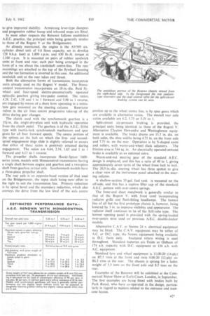
At the rear axle the air suspension bellows are rnounte behind each pair of wheels, as on the Bridgemaster. Ti comparatively rigid framework pivoted amidships und( the body to which the axle and bellows were attached c that model has been replaced by a pair of radius arms i the form of, and occupying the position normally ass( ciated with, laminated springs. These absorb twistir movement only, vertical deflection being catered for E the bellows. They are pivoted on the chassis at the iron but at the rear are attached to the bellows via a fabricah transverse member. The latter also provides one of ti pivot points for a Panhard rod linked to the chassis v a mounting bolted to the rear cross-member and providir lateral location of the rear axle.
Dunlop Pneuride air suspension components are use The bellows are 12-in.-dia. three-convolution units. The upper ends are attached to surge tanks carried in bracke bolted to the frame, which is stiffened at this point by ti two rearmost cross-members. The levelling valves a. linked to the suspension at slightly more than track widi to give improved stability. Armstrong lever-type dampers and progressive rubber bump and rebound stops are fitted.
In most other respects the Renown follows established A.E.C. practice, the principal units being generally similar to those of the Regent V or the Bridgemaster.
As already mentioned, the engine is the AV590 sixcylinder diesel unit of 9.6 litres capacity, set to develop 128 b.h.p. (net) at 1,800 r.p.m. and 430 lb.-ft. torque at 1,100 r.p.m. It is mounted on pairs of rubber sandwich units at front and rear, each pair being arranged in the form of a vee about the crankshaft centre-line. The rear mountings are attached to the top of the flywheel housing and the vee formation is inverted in this case. An additional sandwich unit at the rear takes end thrust.
Both the alternative forms of transmission incorporate units already used on the Regent V model. The Mondcontrol transmission incorporates an 18-in.-dia. fluid flywheel and four-speed electro-pneumatically operated epicyclic gearbox giVing two-pedal control. The ratios. 4,28, 2.42, 1.59 and 1 to 1 forward and 5.98 to I reverse, are engaged by means of a short lever operating in a minia
ture gate mounted on the steering column. Restrictor valves in the air lines ensure progressive take-up of the drive during gear changes.
The clutch used with the 'synchromesh gearbox is a 151-in. dia. single-dry-plate unit with hydraulic operation from the clutch pedal. The gearbox is of the A.E.C. D166 type with inertia-lock synchromesh mechanism and spur gears for all four forward speeds. The centre portion of the splines_on the hub on which the firstand secondspeed engagement dogs slide' is slightly relieved to ensure that either of thesz ratios is positively retained during engagement. The ratios are 4.64, 2.54, 1.65 and 1 to 1 forward and 4.13 to 1 reverse.
The propeller shafts incorporate Hardy-Spicer 1600series joints, models with Monocontrol transmission having a single shaft between engine and gearbox and a two-piece shaft from gearbox to rear axle. Synchromesh models have A three-piece propeller shaft.
The rear axle is an opposite-hand version of that used on the Bridgemaster, the input shaft being now offset to the right to suit the transmission line. Primary reduction is by spiral bevel and the secondary reduction, which also conveys the drive from the low level of the axle centre portion up to the wheel centre line, is by spur gears which are available in alternative ratios. The overall rear axle ratios available are 6.2, 5.75 or 5.35 to 1.
Split-circuit air-pressure braking. is provided, the principal units being identical to those of the Regent V. Alternative Clayton Dewandre and Westinghouse equipment is available. The brake drums are 15.5 in. dia. on both axles, the shoe widths being 4.75 in. on the front axle. and 7.75 in. on the rear. Operation is by S-shaped cams
and rollers, with worm-and-wheel slack adjusters. The friction area is 744 sq. in. An electrically operated exhaust brake is available as an optional extra.
Worm-and-nut steering gear of the standard A.E.C. design is employed, and this has a ratio of 40 to 1, giving approximately seven turns of the wheel from lock to lock. The 20.5-in.-dia. steering wheel has three spokes to give a clear view of the instrument panel attached to the steering column.
A shallow-section 35-gal. fuel tank is mounted on the off-side, and this has a captive filler cap of the standard A.E.C. pattern with over-centre springs.
The front-end sheet metalwork is generally similar to that of the Regent V, with front cowl incorporating radiator grille and flush-fitting headlamps. The bonnet line of all but the first prototype chassis is, however, being lowered by 3 in. to improve visibility and appearance. The radiator itself continues to be of the Still-tube type. The bonnet opening panel is provided with the spring-loaded over-centre strut used on previous A.E.C. double-decker models.
Alternative C.A.V. or Simms 24 v. electrical equipment may be fitted. The C.A.V. equipment may be either of A.C. or D.C. type, the Simms equipment being available in D.C. form only. Insulated return wiring is used throughout. Standard batteries are Exide or Oldham of 174 a.h. capacity with D.C. equipment or 136 a.h. with A.C. equipment.
Standard tyre and wheel equipment is 11.00-20 (14-ply) on B7.5 rims at the front and twin 9.00-20 (12-ply) on B6.5 rims at the rear. The chassis is sprung for a laden weight of 5.5 tons on the front axle and 8.5 tons on the rear.
Examples of the Renown will be exhibited at the Commercial Motor Show at Earls Court, London, in September_ The first examples are being fitted with bodies built by Park Royal, who have co-operated in the design, particularly in regard to matters related to the entrance and staircase layout.