Single-pedal Driving
Page 80

If you've noticed an error in this article please click here to report it so we can fix it.
A UTOMAT1C transmissions allow the
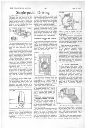
clutch and gear lever to be dispensed with, but two pedals still remain, the throttle and the brake. Patent No. 748,638, shows a device for abolishing the throttle pedal, leaving only one for the driver to work. (Girling Ltd.. Kings Road, Tyseley, Birmingham, 11.) In use, pressing the pedal down works the throttle, whilst allowing it to come up applies the brake. The drawing shows the unit associated with the pedal.
Circulating hydraulic liquid from a pressure pump enters port 1 and after passing across a valve-sleeve reaches the master-cylinder (2) of the hydraulic brakes. This moves the piston to the right and applies the brakes.
When the pedal-link (3) is moved to the right, it progressively opens a bypass (4 and 5) for the fluid so that the brakes are then gradually released. Continued pedal movement gives complete release when the valve land (6) obstructs the inlet.
The engine throttle is worked by a separate small servo-cylinder (7). This is subject to the pressure differential existing across ports 8 and 9. As the brakes go out of action, this pressure rises and the throttle progressively opens.
AUTOMATIC BRAKE ADJUSTER
AUTOMATIC brake take-up is a fairly common practice today, but one possible failing is that overadjustment can occur because of a temporary enlargement of the drums
due to heat expansion. Patent No 747,169 (General Motors Corp., Detroit, Michigan, U.S.A.) shows a scheme by which a high temperature renders the adjustment mechanism temporarily inoperative.
The drawing shows the heart of the
device, which consists of a leftand right-hand-screwed Shoe-spreader fitted with a ratchet-wheel (1). A pawl (2) is moved by the application of the brake, and when the distance moved exceeds the pitch of a tooth, the ratchet is notched round to take up the slack.
So much is well-understood practice, but in the present case the pawl is controlled by a bi-metallic strip (3). When the temperature rises to a serious figure, the pawl is deflected clear of the ratchet teeth and no adjustment then occurs. Another scheme shows the bi-metallic strip designed to give a snap action.
COOLING PISTONS BY ENGINE OIL
AN oil-cooling system for heavy-duty pistons is disclosed in patent No. 748,735, the chief feature being that use is made of the reciprocation to assist in circulating the oil. The patent comes from D. Napier and Son, Ltd., 211 Acton Vale, London, W.3.
The oil arrives primarily from the lubricating system via drilling 1 in the connecting-rod. It passes round a groove and escapes via port 2 into a small chamber. From here, drillings lead to an annular chamber (3).
Oil in this place is shaken by the piston movement and is driven into an enlarged chamber (4). The oil ultimately rises again and finally escapes into the sump through outlets 5. Drillings not shown also connect well 6 with the annular chamber.
EXHAUST ARRANGEMENTS FOR TWO-STROKE ENGINES
PATENT No. 747,788 refers to two-stroke engines having a rotary valve to modify the action of the piston-controlled wail ports. The patent comes from Aldolphe Saurer. Arbon, Switzerland.
It is desirable that such rotary valves shall lie as close as possible to the cylinder-wall ports to minimize dead space. If the rotary valve be built into the cylinder block, it renders it inaccessible for decarbonizing; the essence of the patent is that the valve is built into the exhaust manifold. This not only makes it easy to detach, but also permits the valve to lie very close to the cylinders.
The drawing shows a typical layout in which 1 is the exhaust manifold and 2 the rotary valve, wholly carried therein. The purpose of the valve is to Close the exhaust ports without having to wait until the piston 'rises.
NEW BEARLNIG MATERIAL
PATENT No. 749,529 (C. Faulkner, Tin Research Institute, Fraser Road, PerivaIe, Middlesex), gives details of a composite structure for bearing material. An aluminium ingot has cast on to it a tin-aluminium alloy containing up to 50 per cent. tin. The two metals are then rolled down to the required thickness and bonded to an aluminized steel strip. The latter operation is also, performed by rolling at a temperature below 250°. C.
A CATTLE CONTAINER L'ARM vehicles often have a wide I variety of duties to perform, one of which is carrying cattle. This calls for high walls which can, ofcourse, be temporarily attached, but the resultant fouling of the vehicle may render it unsuitable for other work until it has been cleaned. A cattle container that can be lifted on or off as a unit forms the subject of patent No. 747,815, from Wrights (Gamlingay), Ltd., Biggleswade, Beds, and A. B. Christy and Sons, Middle Farm, Hinxworth, Baldock. Herts.
The drawing shows the container in place on an open vehicle. It consists of three walls and a floor, the fourth wall being made in the form of a rear door. This opens downwards and is so hinged that it can be used as a loading ramp.
The unit is light and easily removed, and the fact that it carries its own floor prevents fouling of the main floor.


