


A Flexible Engine Mounting
Page 56
If you've noticed an error in this article please click here to report it so we can fix it.
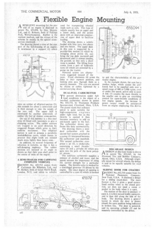
ARESILIENT mounting for the rear end of an engine is disclosed in patent No. 653,094, by Guy Motors, Ltd., and G. Roberts, both of Fallings Park, Wolverhampton. Rubber is the resilient medium, and the virtues of the scheme lie mainly in the special crosssection employed.
The drawing shows a view of the rear part of the bell-housing of an engine. It terminates in a support (1) which rests on rubber of elliptical-section (2 t this extends for about a semi-circle and is thick enough to take the weight of the rear end. The upper half is enveloped by another semi-circle of rubber (3), but of thinner cross-section.
On top of this member is a thin steel strip (4) fitted with tenSioners to give a clamping action. The rubber sections are trapped in an axial direction by staggered flanges which serve to limit endwise movement. The elliptical section is said to possess a parabolic load-deflection curve, which means in practice that slight loads are resisted much more lightly than heavy ones.
In addition, its natural frequency of vibration is variable, so tbat it has a self-damping. tendency. The rubber sections are inclined at an angle as shown so that their axes shall point 1o. the centre of mass of the engine.
used for transporting wheeled loads such as cars. This type of vehicle usually has an upper and a lower deck, and the patent deals with an improved construction of upper deck to facilitate loading.
The drawing shows a vehicle loaded with four cars, two.above and two below. •The upper deck in this case is supported by a parallel-link motion (1) which by swinging about pivots (2), can bring the top deck rearward and downward until it almost touches, the ground, so that only a short ramp is needed. The lifting force comes from a pair of hydraulic rams (3) which are powered by a pump on the tractor.
Powered screws are alternatively suggested instead of the rams. Fixed abutments (4) arrest the links at their topmost position, and locking pins pass though them as a security measure. The cars are secured by chains or cables tightened by a ratchet-carrying drum.
DUAL-FUEL CARBURETTER
T°prevent detonation under fullload conditions is the object of a two-fuel carburetter shown in patent No. 652,733, by Thompson Products Incorporated, Cleveland, Ohio, U.S.A. The patent states that ordinary petrol is quite suitable for high-compression en gin es under light load, but as the throttle is opened it then becomes necessary to add an anti-knock agent to the fuel. The carburetter shown performs this duty automatically.
The drawing shows a standard carburetter with the second fuel system attached to a,easing (1) interposed between the carburetter and manifold. This second carburetter cornprises a jet '(2), a choke-tUbe. containing a small throttlevalve (3) and a jet-tube (4) which projects into. the path of the 'Main petrolair stream.
The auxiliary carburetter supplies a mixture of alcohol and water, and the patent stresses the importance of using the 'correct strength for a particular engine. The throttle-valve is worked by a centrifugal governor (5) driven by the engine. The exact degree of opening is controlled by a cam (6) which is formed DISC-BRAKE DESIGN
,A DESIGN of disc-type brake is shown :A in patent No. 653,245, by the Firestone Tire and Rubber Company, Akron, Ohio, U.S.A. Although originally meant for aircraft wheels, the design is said to be equally suitable for road vehicles.
SLIDING DOOR FOR COACHES
PATENT No,652,710 comes from the National Pneumatic Company, New York, U.S.A. It discloses a design for a sliding coach-door, The main feature is that it gives a good streamlined outline when in the closed position, yet does not need a recess or pocket in the body when it is open. The motion of the door is unusual; to open it, it is first moved bodily outwards, and is then slid along the side of the body. The drawing shows a general layout in which the door is shown closed, the open position being indicated in broken line. The door Is powered, and its operating cylinder (1) can be remotely controlled by the driver.