


Multi Bus-ticket Issuing Machine
Page 36
If you've noticed an error in this article please click here to report it so we can fix it.
A Résumé of Patent Specifications That Have Recently Been Published
ACONDUCTOR'S ticket issbing machine forms the subject of patent No. 568,805, which comes from the Bell Punch Co., Ltd., A. Weaves and C. Webb, all of 39, St. James's Street, Lotion, S.W.1. The aim of the design is to provide the largest number of types of ticket without calling for extreme mechanical complexity.
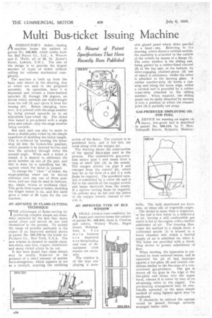
The machine is built up from the basic unit shown in the drawing, five of which are used in the proposed assembly. In operation, lever I is depressed and rotates a three-toothed sprocket (2) through 120 degrees, an action which unwinds one ticket-length from the roll (3) and ejects it from the issuing slot. Before emerging, however, it is printed with the stage number
• by being pressed upwards on to an adjustable type-wheel (4). The ticket thus issued is pre-printed with a single price and colour, only the stage number being variable.
But each unit can also be made to issue a double-price ticket by the simple expedient of doubling the ticket length. This is achieved by moving the leverstop (5) into the broken-line position, which permits it to descend farther an.d turn the sprocket through twice the normal angle. When such a ticket is issued, it is desired to obliterate tfie serial number on one of the pair, and this is done by a cancelling bar (6), against which the ticket is pressed.
To change the " class "of ticket, the stage-printing wheel can be moved sideways into any one of :three positions, and can thus be used to indicate, say, single, return or workman class. This gives three types of ticket, doubling the length makes it six, and five units gives a total of 30 types for the one machine.
AN ADVANCE IN FLAME.CUTTING TECHNIQUE
THE advantages of flame-cutting for producing complex shapes are somewhat curtailed by the fact that many useful alloys and metals do not lend themselves to the process. To extend the range of possible materials is the object of an improved method shown in patent No. 568,720 by the Linde Air Products Co., New York, U.S.A. The new scheme is claimed to enable stainless steels, cast iron, copper, aluminium and many nickel alloys to be cut.
It has been found that these metals may be readily flame-Cut in the , presence of a small amount of molten ferro-manganese, which appears to act as a catalyst, assisting the oxidizing action of the flame. The catalyst is in powdered form, and is fee into the work along with the oxygen jet.
The drawing shows the construction of the special blow-pipe used in the process. The combustible gas-acetylene enters .pipe 1 and issues from a ring of small jets (2) in the notate. The oxygen arrives via pipe 3 and emerges from the central jet, which may be in the form of a slot if a wide flame be required. The powdered catalyst is controlled by a valVe (4) and is fed to the outside of the oxygen stream and issues therewith from the nozzle. If a narrow cutting flame be required, the poivder may be Jed into the centre of the oxygen stream, instead of outside it.
AN IMPROVED TYPE OF BUS WINDOW
ASMALL window-cum-ventilator for buses and coaches forms the subject of patent No. 568,824, from A. Cheston and others, Widney Works, Bagot Street, Birming, ham, 4. The main features a r e improved we a therproofing and ease of detachment 'Whe'n repairs are necessary.
The window is of the type employing a mov
able glazed panel which slides parallel to a fixed one. Referring to tl.e drawing, which shows a vertical section, the assembly is attached to the outside of the vehicle by means of a flange (1). The outer window is the sliding one, being guided by a rubberqined channel (2) at the top and, at the bottom, by inter-engaging channel-pieces (3) one of wilich is stationary, whilst the other is attached to the moving glass. A rubber weather-strip (4) forms a running seal 'along the lower edge, whilst a vertical seal is provided by a rubber wiper-strip attached to the sliding member. When required, the sliding panel can be easily detached by moving it into a position in which the channel joint (3) is partially cut away.
GAS-PRODUCER EMPLOYING OIL FOR FUEL
ADEVICE for running an engine 4.,n heavy, low-grade fuel is described in patent No. 568,519, by T. Nair, Thirunelli Estate, Kalpatta, Malabar,1
India. The fuels mentioned are kerosene, or other oils of vegetable. origin. . The device is more than a vaporizer,
as the fuel is burnt in a deficiency of air, leaving a still combustible gas which is fed to the engine, with a further admixture of air. The drawing illustrates the method in a simple form; a calibrated nozile (1) is housed in a lower chamber. into which a limited supply of air is admitted via inlets 2. The latter are provided with, a throttling device to permit adjustment of flow.
When starting, the apparatus is preheated by some external means, and in operation the jet of fuel, impinges against a hot plate (3) and creates conditions similar to the fire-zone of a conventional gas-producer. The gas is drawn off via gaps in the edge of the hot-plate and issues into the upper hood, whence it is taken by way of an air-mixing valve to the engine. The pre-heating arrangement may be electrically operated, or the more simple method of using lighted spirit may -Fe employed.
If electricity be utilized the current would be passed through suitably arranged heater coils.