


ALTERNATIVE DESIGN FOR GLASGOW TRACTOR.
Page 28
If you've noticed an error in this article please click here to report it so we can fix it.
A Résumé of Recently Published Patents.
For the benefit of readers who are not very well acquainted with the features of the Glasgow tractor, we would recall that it is a three-wheeled machine having two wheels before and one behind. All three are driven. There is no differential, and the special feature of its censtruction is that, when on the turn, the rear wheel tracks with the outer of the two front wheels. It is a machine which has excited considerable interest wheiever it has been seen, arid particular advantage arises from the all-wheel drive, inasmuch as there is not the same difficulty in negotiating abrupt turns at the-headlande.
There is published this week patent specification No. 143,419, the patentee being D. kIeNaughton Wallace. which describes a tractor possessing most of the features of the Glasgow, with this outstanding point of difference, that. the single steering wheel is at the front, and the two wheels at the rear. The re-arrangement of these wheels in. volves, as might be expected, certain detail alterations in the construction of the transrniseion mechanism. Several of these alterations are worthy of note, particularly the provision for altering ehe elevation Of tU near and . off side rear wheels, so that the tractor may be levelled, notwithstanding that one of its rear wheels may be running in the bottom of a. ploughed furrow, while the other runs on the eurface of the untilled land. We will, however, take the various points' in succession.
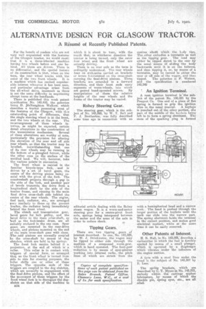
The front wheel is carried in the familiar bicycle-typo fork, and is driven bya set of bevel gears, the centre of • the driving pinion being coaxial with the pivot of the fork. The countershaft projetts through a gap in the aide of the -fork, and another pair of bevels transmits the drive from a longitudinal shaft by the aide of the tractor frame, and running fo the main final drive cross-shaft side behind the centre ef the rear wheels. The engine, fuel tank, radiator, etc., are arranged very similarly to those on the prevent tractor, the -radiator being immediately behind the front wheel.
The einteli and transmission gear, bevel gears for belt pulley, and. the bevel drive to the main cross-shaft, as 'well as the foot-brake drum, are all isuitably enclosed in the one cane. Spur gears. are mounted inthe rear-cifive wheels, and pinions mounted on the end of the main cross-shaft gear with them. The said pinions are normally coupled Ito. the cross-shaft by means of dog clutches, which are held in by springs.
The front fork carries behind it a projection. at the end Of which is a roller. This roller is in contact with triggers of special form, so arranged that as tho 'front wheel ie turned from side to side for steering purpoees, the 611e1 ehifts one or other of these triggers. The opposite ends of the triggers are coupled to the dog clutches, which are normally in engagement with the final drive pinions, and the effect of the movement of these triggers by the front wheel, fork is to disengage the dogclutch on that side of the maehine to B34 which it is about to turn, with the result that; in whichever direction the tractor is being tinned, only the outer tsar wheel and the front .wheel are actually driving.
There is no rear axle as the teem is ordinarily understocd. The rear wheels bear on stub-axles carried on bracketsor levers fulcrummed on . the cross-shaft carrying the final-drive pinions. These brackets are extended in a forward direction, and their front ends carry segments of worm-wheels, into .which
are geared hand-operated screws. By manipulation of the,* the relative heights of the rear wheels and the frame of the tractor may be varied.
• Robey Steering Gear..
The steering gear, which is the subject of No. 143,393, by W. T. Bell and I`, Brethertim, was fully described some time ago in connection with an editorial article dealing with the Robey steam wagon. It is a worm-and-sector steering gear for a centre-pivot front axle, springs being interposed between the sector and the arms of the axle in order to reduce shock.
Tipping Gears.
There are two tipping gears of interest described. In one, No. 145,329, by W. 5. Driokwatcir, the wagon may be tipped to either side through the medium of a compound worm-gear, which is hand operated. The final-gear reduction is by means of spur-pinions working into internal racks,. the pitch lines of which are struck from the centres a-botft which the body tips. The other embodies a turntable as well as the tipping gear. • The load may either be tipped direct to the rear by the usual means eif sliding the body -backwards until it is on the balance, and then tipping it, or, by means of a turntable,. may be turned to either the near or off side of the wagon,' and then tipped. The patentee is K Watson, and the specification is numbered 143,342
An Ignition Terminal.
A neat ignition terminal is 'the subject of the patent No. 130,321 by the Peugeot Co. One end of a piece of fiat spring is formed to grip the ignition wire in the usual manner. A keyhilie is punched out of the other portion, one part of the middle of the keyhole being left in to form a spring abutment. The stem of the sparking plug is formed with a hemispherical head and a narrow neck. The head is pushed through the, larger portion of the keyhole until the neck can slide into the narrow part. The spring abutment holds the terminal in the correct position., and makes good electrical 'contact, while at • the same time it can be easily removed.
Other Patents of Interest.
H. H. Hall, in No. 143,206e. describes a carburetter in which the fuel is forcibly 'ejected by means of a small plunger, which is operated by a diaphragm which vibrates under the influence of the engine suction.
A tyre with a steel lifter tinder the tread is the subject of No. 143,307 by K Lees.
The spring brackets, which are described by C. T. Myers in No. 143,373, embody within the castings syphon lubricators, by means of which the shackle pin, spring eyes, etc., are all