


MAGNETIC POWDER CLUTCH .
Page 80
If you've noticed an error in this article please click here to report it so we can fix it.
A MAGNETIC clutch forms the subject
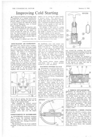
of patent No. 854,065. the layout permitting high transmission torque to be obtained from a unit of relatively small dimensions (S. Smith and Sons (England), Ltd., Cricklewood Works, Cricklewood. London, N.W.2).
In the drawing (I) is the driving member which in this case is the flywheel of an engine. Outer casing (2), a nonmagnetic separating wait (3), and an end plate (4) rotate with this on ball races (5 and 6).. Fixed to the inside of the outer casing are windings (7) which can be energized to create a magnetic field.
The driven members are a pair of Ushaped annuli (8) attached to . the central shaft. The gaps between the driving and driven members are filled with magnetic powder retained by -a labyrinth seal around the windings, the powder being prevented from escaping inwards by the magnetic field produced by rings (9) which are permanent magnets.
When the windings are energized a toroidal field is produced, passing through the outer casing (2) and driven member! (8), and this causes the powder to solidify in the narrow air gaps (10) and sc transmit the torque applied..