


Fluid Drive With Positive Coupling
Page 72
If you've noticed an error in this article please click here to report it so we can fix it.
WHILST the hydraulic coupling VT gives a smooth torque at starting, its relatively low efficiency in top gear is a disadvantage. A scheme in which an automatic clutch is used to give a straight-through drive in these circumstances is shown in patent No. 740,363 (Leyland Motors, Ltd., Suffolk House, Laurence Pountney Hill, London, E.C.4.).
The coupling is centrifugally operated, but the use of this principle often results in an intermediate slipping speed which wears the clutch unduly. The present scheme gets over this by using compressed air as a servo power to provide a quick action. The drawing shows a standard torque-converter, the two elements Of which can be locked together when a presser disc grips a clutch disc (2). The presser disc is operated by a flexible diaphragm (3) when air is admitted to the right-hand side of it. The compressed air supplied via a rotary seal on the shaft and is controlled by a centrifugally operated valve located in housing 4. It comprises a spring-loaded, slide-valve which, when moved by centrifugal force, admits compressed air to the side of the diaphragm.
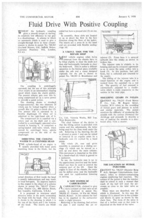
DIRECTING THE COOLING WATER IN A CYLINDER HEAD
T"ylinder-head of an engine is usually provided with water ports matching those in the block, but the actual direction of flow inside the head is usually indeterminate and may result irk local hot-spots. To improve matters in this respect is the object of a scheme shown in patent No. 740,117 (Caterpillar Tractor Co., 800 Davies Street, San Leandro, California, U.S.A.). It is proposed to interpose small directive tubes in the ports connecting the bloFk with the head. Oneof these is shown in the drawing in which 1 is the top of the block and 2 the bottom of the head. The inserts are blind
c32
ended but have a pressed slot (3) on one side. In assembly, these slots are located o as to divert the flow in the best direction along the floor of the jacket. The inserts are a press fit in the head
provided with flexible sealingand are
rings (4). .
.A USEFUL TOOL FOR THE REPAIR SHOP
IkAOST vehicle engines when being .1V1 removed from the chassis have to be lifted slightly to clear the studs and then slid horizontally forwards to clear
w
the bodywork. This is rather a difficult operation in the limited space available
ne
under the cab and a crane designed expressly for the job is shown in patent No. 740,503 (J. Brockhousc and Co., Ltd., Victoria Works, Hill Top. West Bromwich). The chief feature of the device is that the lifting action is provided with coarse and line adjustments, the latter being used for the close Work under the cab. Referring to the drawing, the jib is pivoted at point 1 and can be raised or lowered in an angular sense by a hydraulic ram (2) worked by a hand pump. The whole jib, ram and pivot a assembly is mounted on sliding carriage (3) which can be moved as a unit up and down the main column. This movement is imparted to the slide by a hand-wheel (4) which geared to a jackscrew.
In use, the hydraulic ram is set to the approximate position and the handwheel can then -be used to control the
accurate part of the lift. Once the engine is clear of the chassis, the crane can be pulled away and the hydraulic ram used for ,rapid-motion lowering or ,raising.
A-NEW SYSTEM OF CARBURATION A CARBURETTER, claimed to give PIa more constant air-fuel ratio at all speeds, is disclosed in patent No. 740,036 (C. Gianini, 14 Via del Monti Parioli, Rome).In this scheme the fuel has to be Aippliedl to the carburetter under a slight pressure. . Referring to the drawing, fuel arrives via pipe 1 and reaches the jet or hjector (2). From here it is sprayed upwards into the intake as shown in
broken line. •
The injector tube is slidable in its housing and can be .retracted rightwards so as to move the spray orifice into a hood (3). In this position, fuel still flows, but is collected and returned to he supply. The sliding of the injector tube is a limed function of the engine and is worked from the camshaft via a rod (4). The quantity of fuel pumped is automatically adjusted by a needlevalve which is made responsive to the suction in the inlet pipe.
MOULDING GEARS IN NYLON
pTENT No. 739,253 (Ford Motor Co., Ltd., 88 Regent Street, London, W moulding ofrefers to the mulding of helical gears and pinions in nylon and similar materials. The patent mentions the difficulty of producing the moulds with the correct allowance for shrinkage and proceeds todescribe a way of making the moulds in a zincbased alloy from a master.
THE LOCATION OF PETROL INJECTORS
.DATENT No. 740,327 (Daimler Benz I A.G., Stuttgart Unterturkheirn, Germany), refers to mixture-compressing engines employing fuel injection. The essence of the patent is that the injector shall be aimed in such a manner that much of. the fuel will meet the airstream as close to the inlet valve as possible. Three ways are described, one of which is illustrated. hi this case the injector (1) is placed low in the cylinder and directs its spray as shown by the chain lines. The form of the spray is that of a hollow cone so that none is deposited on the head of the valve.