


A New Electro-magnetic Clutch
Page 60
If you've noticed an error in this article please click here to report it so we can fix it.
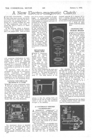
LECTRO MAGNETIC clutches have often been mooted, but nearly all of them call for some type of rotary pick-up for the energizing current. A design' fOr a clutch avoiding the need for this -troublesome item comes in patent .No. 629,311, from S. A. Andre Citroen, Paris.
In the drawing, which is diagrammatiC, 1 is The engine-driven' member and 2 the output shaft. Both are fitted
with numerous. clutch-plates in interleaved drder, pressed into the free position by a spring(3). Enclosing both members is a pot-magnet (4) energized by a Concentric winding (5). This magnet isstationary, so that no complication is 'involved in its conitec
tion;:
In operation, when the coil is energized, the two sets of clutch-plates become magnetized to opposite polarites, exert a mutual attraction and move into driving contact. A gentle engage-merit can be obtained by including a rheostat in the energizing circuit.
TURNING NON-CIRCULAR SECTIONS IN A LATHE THERE are many components which, although produced mainly by turning, have at one point a non-circular shape such as a square, hexagon or flat. Usually, this means a second operation on another machine, unless the lathe be fitted with some means for producing it. Such a device is shown in patent No. 629,081, by A. frevena, and J. Brockhouse and Co., Ltd., Victoria Works, Hill.Tcy, West Bromwich. . bore (2) to receive a workpiece of some length. A spring-loaded tool-holder unit (3) is provided with a projection (4) which engages an internal cam-track (5) mounted on the spindle.
In operation, the work is presented to the lefthand side and is turned by the oscillating tool which thus produces the required non circular shape. The form is, of course, entirely dependent upon the earn contour, and a special cam has to be used for each set-up. In view of this requirement, the cam is readily detachable by undoing a few grub-screws as indicated at 6.
DETACHABLE WHEEL RIMS
FRON{ P. Chatterton, and the Dunlop Rubber Co., Ltd., 1, Albany Street, London, N.W.I, comes patent N9. 629,786, which deals with an improved design for a rim baying a detachable side. . The drawing shows a cross-section of ! the rim, which comprises the main part with the addition of a detachable sidemember (1). The body has attached to it a ring (2), which is welded on at point 3. The chief feature of the
scheme is that the uniting bolts are located on the line of weld, aposition which is said to .give the maximum strength to the assembly.
A UNIVERSALLY JOINTED "GUDGEON-PIN"
A SPHERICAL " gudgeon-pin" is I-1 shown in patent No. 629,536, which comes from I. Wooler, Willow Bungalow, Ruislip, Middlesex, Although intended mainly for swash-plate engines, the inventor states that as the piston is free to revolve, uniformity of wear occurs; this would be an advantage in any engine.
The drawing shows an exploded view of the assembly. A part-spherical ring (1) rests on a shoulder in the piston, and forms a bearing for the end 2 of the connecting rod. A spherical ring (3), split for ease of assembly, is clamped upwards by a ring-nut (4) to leave a working clearance for the rod. The assembly is locked by a spring-ring (5) the end of which penetrates into one of a series of holes drilled round the piston skirt.
COUPLING FOR ' TRAILER 'BRAKES
ONE of the problerns arising in ,the operation of trailer, brakes is that of ensuring
• equality, or some constant ratio, between the forces used on tractor and trailer. An ingenious method of coupling the two sets of brakes forms the .subject of patent No. 630,231, which comes front C. Rydh, Virserurn, Sweden.
In this scheme, the reaction of the brakes on the, tractor vehicle is used. to power the brakes on the trailer, so that the trailer brakes are operated exactly' in accordanee with the actual braking effort of the tractor. • The drawing shows one, of the
driving hubs of the tractor. The brake on this is worked by one. of the standard mechanisms, but the construc tion differs from the normal in that the back-plate (1), instead of being fixed, 'Is free to to& on the axle tube. The rocking motion is transmitted by a shaft carrying levers (2 and 3) to a master hydraulic cylinder (4).
This cylinder is the motive unit of the trailer brakes, to which it is connected by flexible piping. In operation, when the tractor is braked, the back-plate tends to revolve, and so imparts a force to the master cylinder. An ingenious link motion (5) is incorporated in the rodwork, its object being to work the master cylinder in the same direction whether the vehicle be moving forwards or backwards.
It must be understood that the degree of braking between tractor and trailer must be correctly proportioned.,