


1939 OPENS WITH A FLOOD OF PROMISING INVENTIONS
Page 32
Page 33
If you've noticed an error in this article please click here to report it so we can fix it.
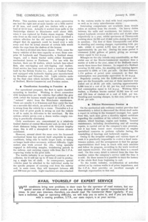
DESIGN FOR MAINTAINING CONSTANT COMPRESSION PATIO.
obtain maximum thermal effici ency at all loads, it is necessary to maintain the compression ratio at a constant value, and patent No. 495,859 (void), discloses a scheme whereby this is attained. The patentee is K. Tsuneda, Kyoto, Japan. The drawing shows a section of the engine, in which the compression can be adjusted by means of an inverted screw-operated piston. (9). The piston is set by the rotation of a nut (4) formed externally as a spur gear and meshing with a sliding rack (I), which forms the common control to a row of cylinders.
The patent also describes an automatic controller, operated by engine suction or exhaust pressure, the servo-cylinder of which is seen at 2 in the drawing, A basic feature of the patent is the use of electrically operated control valves in the servo-cylinder system.
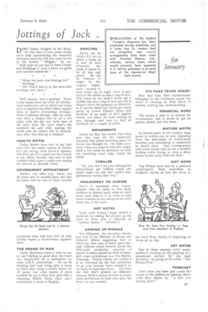
NOVEL LOW-PRESSURE INJECTION SYSTEM.
AN injection pump must not only be accurate, hut must be extraordinarily robust, and efforts to co-ordinate these two requirements result in a high-priced unit. A scheme in which low-pressure injection obviates the need for a powerful pump is disclosed in patent No. 495,501, by G. Kammer, of Budapest, Hungary. This inventor proposes to inject the fuel into a small volume of lowpressure air in a separate chamber, and, when the piston arrives at the top dead centre, a connecting valve is to be opened, thus causing self-ignition of the fuel in the chamber.
The cycle of operations is as follows :—When the piston is at bottom dead centre, a valve (3) descends, drawing air from the cylinder, via a port, into an increasing space (2). As the piston rises on compression, this space is isolated by a port (1) and a low-pressure injection is made via a central bore (4). This is achieved in a simple manner by arranging a pump plunger (5) to be held stationary in the stem of the e2Ei descending valve. Injection ends as the main piston reaches top dead centre, and the valve (3) re-ascends and releases the compressed air into space (2); this ignites the charge and thereafter operates as a, pre-combustion-chamber engine. The injection is regulated by adjusting the height of the plunger (5) by means of a lever (6).
PROGRESS IN OXY-HYDROGEN ENGINES.
FOR some time past the Erren Engineering Co., Ltd., 423, Abbey House, London, S.W.1, has been experimenting with engines designed to run on a mixture of oxygen and hydrogen, and patent No. 496,120, from this concern and W. von Rosenberg, discloses an engine of this type that can also be operated on oil fuel.
In the oxy-hydrogen cycle, a threeway cock (7) is set in the position shown, and oxygen, arriving via a pipe (1), is drawn into the cylinder through a normal inlet valve, On the first part of the compression stroke, hydrogen is injected through a port (4) and forms a highly cothbustible mixture. At the end of the power stroke, some of the combustion product (steam) escapes, via a valve (5), into a steam reservoir (6), whence it is used to dilute the next oxygen charge. The rest of the steam passes, during a normal exhaust stroke, to a condenser (3), where' a vacuum is created; this provides a second and minor power stroke, the piston being sucked upwardly instead ot having to contend with back pressure.
When operated on oil fuel, the cock (7) is turned to admit air instead of steam, and fuel is supplied from an injector (2), the sparking plug then being unnecessary. It is also possible to run the engine on gas, this being introduced via the hydrogen port (4).
PROTECTING. 'THE CONTROLS FROM ROAD SHOCKS.
LN a heavy motor vehicle it sometimes happens that the steering column, attached as it is to a frame bracket at a point near the front axle, transmits road shocks and vibrations to the driver. To avoid this is the object of a scheme disclosed, in patent No. 495,736, by the MetropolitanCatnniell Carriage and Wagon Co., Ltd., and others, of Saltley, Birmingham.
In this arrangement, the driver's 'controls—steering, pedals, and brake levers—are •attached to a small subframe, instead of to the main chassis longitudinals. The subframe is attached, at the rear end, to the main frame, but the forward end is carried by a front body member. The drawing shows the general layout, in which 1 is the floor of the cab, 3 the forward point of attachment of the subframe, whilst the rear end (2) is drilled to receive frame bolts. NOVEL TWO-STROKE ENGINE HAVING TWIN PISTONS.
PATENT No. 496,005, discloses a design of two-stroke twin-piston engine, and comes from J. Ehrlich and the Works Development Co., Ltd., 2, York Street, London, W.I. Referring to the drawing, the engine comprises a pair of cylinders connected to a common combustion space (5). The two pistons are connected to a common crankpin, but the Y-shaped connecting rod causes one piston to lead the other in phase by a few degrees. The lower end of the crankcase is provided with a short piston of large diameter (4); this acts as a charging pump.
In operation, mixture is drawn into the crankcase, via a.flap-valve (3), and is compressed by the lower piston. From the crankcase the compressed mixture is led to a cam-operated inlet valve (1) , whence it passes into the cylinders. Exhaust takes place out of a pair of ports (2); owing to the phase difference between the pistons these ports can be made much shorter than usual, and so a power stroke of increased duration can be obtained.
PROGRESS IN SLEEVE-VALVE OIL ENGINES.
THE possibilitie oil engine are gated, and paten
s of the sleeve-valve still being investi
t No. 495,541 shows something of the latest suggestions for this type of power unit. The inventor, A. de Sampaio, 8, Chester Place, London, W.2, claines that his 4esign provides for a simple form of construction, with lessened friction, and easier lubrication than hitherto has been obtainable.
The drawing . shows a section of the cylinder, with the sleeve and crank mechanisms set out diagrammatically. The engine employs two concentric
sleeves, an inner one (2) in which the piston moves, and an outer one (6). which is 'short enough to be referred to as a collar. The two sleeves are driven by small cranks (4 and 5) and, by their combined action, open a ring of ports (3) alternately to intake (7) and exhaust (1), in a known manner. The cylinder head is stationary, but penetrates rather deeply into the cylinder.
STEERING ARRANGEMENTS FOR ENDLESS-TRACK VEHICLES.
THE method usually adopted for steering an endless-track vehicle is to brake one of the tracks, but this system often results in harsh and violent change of direction. An ingenious way of avoiding this is shown in patent No. 495,861 (void) by the Tatra concern, of Prague, Czechoslovakia. In this scheme, a pair of epicyclic reduction gears (2) is mounted on each axle shaft, and by selectively operating one or two on one side, one axle is made to revolve at a lower speed, thus giving a constant and steady turning action. Drums (I) serve as the normal braking system.
AUXILIARY LUBRICATION OF • ENGINE CYLINDERS.
A CCORDING to patent No. 496,099,
there are two distinct conditions under which the usual lubrication system of an engine is least effective; these are, at starting, when the oil is cold, and during protracted periods of full-load running, when the oil may be temporarily thinned out as the result of high engine temperature. The patentee, W, Gothe, Niebuhrstrasse 78, Berlin, describes an auxiliary cylinder-lubricator which functions only during the above-mentioned periods.
In the drawing, which shows the apparatus mounted on top of the cylinder block, an oil-supply pipe (6) leads to a spring-loaded valve (5), and thence to the intake pipe (3) of the engine. The valve controls the supply of extra oil, and can be opened by two methods—lever 4, which is controlled by a thermostat (2), when starting from cold, and lever 1, which is moved only when the throttle is fully open; this provides the extra oil for full-load work.
ADJUSTING INJECTION-PUMP TIMING CENTRIFUGALLY.
ACENTRIFUGALLY operated advance mechanism, for the drive of an injection pump, forms the subject of patent No. 495,400, by the Hesselman Motor Corporation, Ltd., 56, Kingsway, London, W.C.2. Whilst such devices are quite common, it is claimed for this one that the angular adjustments are made with a high degree of precision, whilst, at the same time, a large displacing force is
generated. • • The device comprises two main parts, a hub (not shown) which carries the pivot pins (I) and which forms the engine-driven member, and the outer casing, which is internally toothed in two opposite sectors and is attached to the spindle of the pump. The bob-weights (2) are correspondingly toothed, and as they fly outwards centrifugally, they rotate the outer casing with respect to the hub. An essential feature of the patent is the arrangement of the springs; these connect the long sides of each bob-weight with the short sides, as shown.