


Combining Epicyclic Gear and Clutch
Page 62
If you've noticed an error in this article please click here to report it so we can fix it.
A Résumé of Recently Published Patent Specifications
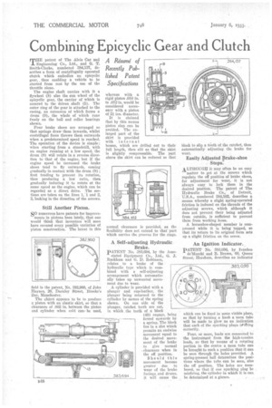
rnHE patent of The Alvis Car and Engineering Co., Ltd., and G. T. Smith-Clarke, numbered 384,137, describes a form of centrifugally operated elu,tch which embodies an epicyclie gear, thus enabling a vehicle to be started from rest by the use of the throttle alone.
The engine shaft carries with it a flywheel (8) also the sun wheel of the e-picyclic gear, the carrier of which is secured to the driven shaft (5). The outer ring of the gear is attached to the casing, an extension of which forms a drum (9), the whole of which runs freely on the ball and roller bearings shown.
Pour brake shoes are arranged so that springs draw them inwards, whilst centrifugal force throws them outwards when a predetermined speed is reached. The operation of the device is simple; when starting from a standstill, with an engine running at a low speed, the drum (9) will rotate in a reverse direction to that of the engine, but if the engine speed be increased the brake shoes tend to fly outwards, coming gradually in contact with the drum (9) ; first tending to prevent its rotation, thus producing a low ratio, then gradually inducing it to rotate at the same speed as the engine, which can be regarded as a direct drive. The sections are taken on the lines 1, 1 and 2, 2, looking in the direction of the arrows.
Still Another Piston.
SO numerous have patents for improve ments in pistons been lately, that one would think that inventors will soon have covered every possible variation of Piston construction. The latest in this field is the patent, No. 382,960, of John Haynes, 20, Darnley Street, Brooks's Bar, Manchester.
The object appears to be to produce a piston with an elastic skirt, so that a clearance of .002 in. between the piston and cylinder when cold can* be used, whereas with a rigid piston .010 in. to .012 in. would be considered necessary with a piston of 2i ins. diameter.
It is claimed that by this means piston slap can be avoided. The enlarged part of the skirt is provided with internal bosses, which are drilled out to their full length, then slit so that the skirt is slightly compressable. The part above the skirt can be reduced so that normal clearance is provided, as the flexibility does not extend to that part which carries the grooves for the rings.
A Self-adjusting Hydraulic Brake.
PATENT No. 383,694, by the Asso ciated Equipment Co., Ltd., G. J. Bukhara and G. D. Robinson, relates to a brake of the hydraulic type which is combined with a self-adjusting arrangement which automatically takes up unwanted movement due to wear.
A cylinder is provided with a plunger and cup-leather, the plunger being returned to the cylinder by means of the spring shown. On one side of the Plunger, ratchet teeth are cut, in which the teeth of a block (48) engage, being forced upwards by a spring. The block lies in a slot which permits an endwise movement equal to the desired movement of the brake to give normal clearance when in the off position.
Should this movement become greater due to wear of the brake facings, and drums, it will cause the block to slip a fiioth of the ratchet, thus automatically adjusting the brake for wear.
Easily Adjusted prake-shoe Stops.
ALTHOUGH it may often be an easy matter to get at the screws which regulate the off position of brake shoes, for adjustment for wear, it is not always easy to lock them in the desired position. The patent of The Hydraulic Brake Co., of Detroit, U.S.A., numbered 384,102, describes a means whereby a slight Spring-operated friction is induced on the threads of the adjusting screws, which although it does not prevent their being adjusted from outside, is sufficient to prevent them from working loose.
A horseshoe-shaped member is compressed while it is being tapped, so that its return to its original form sets up a slight friction on the screw.
An Ignition Indicator.
PATENT No. 383,036, by Ivanhoe del.larchi and B. Brown, 60, Queen Street; Horsham, describes an indicator
which can be fixed in sonie visible place, so that by turning a knob a neon tube will be made to glow as an indication that each of the sparking plugs is, 11`ring correctly. •
Four, or more, leads are connected to the instrument from the high-tension leads, so that by means of a rotating portion in the centre a neon tube can be brought to such a position that it can be seen through the holes provided. A spring-pressed ball determines the positions where the tube can be seen, also the off position. The holes are numbered, so that if one sparking plug be misfiring, the cylinder in which it is can. be determined at a glance.